
5
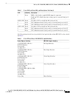
Cisco 1721, 1760, 2621XM, 2651XM, 2691, 3725, and 3745 Modular Access Routers and 7206-VXR NPE-400 Router FIPS 140-2 Non-Proprietary
OL-6083-01
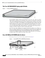
The Cisco 1721, 1760, 2621XM, 2651XM, 2691, 3725, 3745, and 7206 VXR NPE-400 Routers
Cisco IOS features such as tunneling, data encryption, and termination of Remote Access WANs via
IPSec, Layer 2 Forwarding (L2F) and Layer 2 Tunneling Protocols (L2TP) make the Cisco 1700 an ideal
platform for building virtual private networks or outsourced dial solutions. Cisco 1700`s RISC-based
processor provides the power needed for the dynamic requirements of the remote branch office.
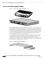
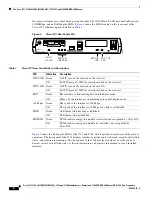
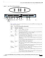
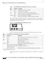
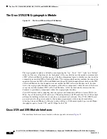
Cisco 1721 and 1760 Module Interfaces
The interfaces for the router are located on the rear panel of the Cisco 1721 and the front panel of the
Cisco 1760 as shown in
Figure 3
.
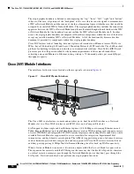
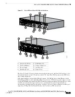
Figure 3
Cisco 1721 and Cisco 1760 Physical Interfaces
The Cisco 1721 and 1760 routers feature console and auxiliary ports, single fixed LAN interfaces, two
Cisco WAN interface card (WIC) slots on the 1721, and two WIC slots and two Voice interface card
(VIC) slots on the 1760. WAN interface cards support a variety of serial, ISDN BRI, and integrated
CSU/DSU options for primary and backup WAN connectivity. All Cisco 1700 series routers include an
auxiliary port supporting 115Kbps Dial-On-Demand Routing, ideal for back-up WAN connectivity.
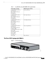
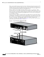
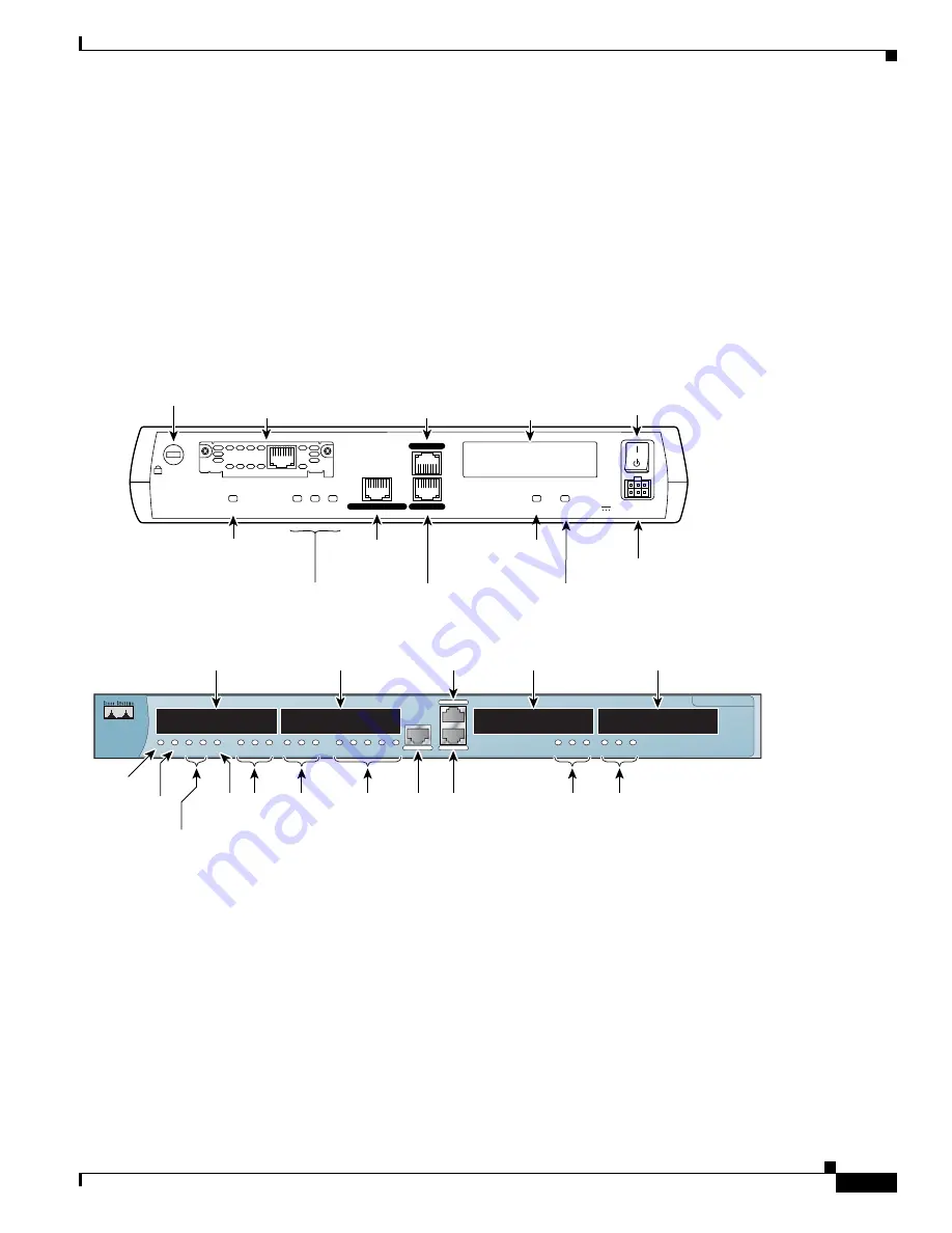
A WIC is inserted into one of the WIC slots, which are located on the back panel of the 1721 and the
front panel of the 1760. WICs interface directly with the processor, and cannot perform cryptographic
functions; they only serve as a data input and data output physical interface.
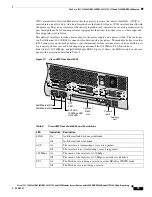
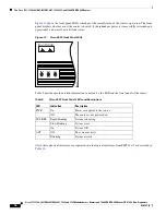
The physical interfaces include a power plug for the power supply and a power switch. The router has
one Fast Ethernet (10/100 RJ-45) connector for data transfers in and out. The module also has two other
RJ-45 connectors on the back panel for a console terminal for local system access and an auxiliary port
Cisco 1700
Series
10/100 ETHERNET
AUX
CONSOLE
PWR
OK
PVDM 0
OK
PVDM 1
OK
MOD
OK
ACT
COL
FDX
100
LINK
SLOT 0
OK
0
1
SLOT 1
OK
0
1
SLOT 2
OK
0
1
SLOT 3
OK
0
1
99391
THESE SLOTS ACCEPT ONLY VOICE INTERFACE CARDS
Power
socket
+5, +12, -12 VDC
CONSOLE
10/100 ETHERNET
AUX
FDX
LINK
100
WIC 0 OK
WIC 1 OK
MOD OK
Power switch
Model
Cisco 1721
65524
FDX/100/
LINK LEDs
WIC/VIC Slot 0
WIC/VIC Slot 1
VIC Slot 2
VIC Slot 3
Slot 3
LEDs
Slot 2
LEDs
Slot 1
LEDs
Slot 0
LEDs
PVDM 0/1
OK LEDs
MOD
OK LED
Router
OK
Power LED
Auxiliary port
Auxiliary
port
Ethernet
port
Ethernet
LEDs
Kensington-compatible
locking socket
WIC 0
OK LED
10/100-Mbps
Ethernet port
MOD OK
LED
WIC 1 OK
LED
WIC 0 slot
WIC 1 slot
Console port
Console port
SEE MANUAL BEFORE INSTALLATION
DSU
56K
CD
AL
LP
RD
TD


