


22
Cisco 1721, 1760, 2621XM, 2651XM, 2691, 3725, and 3745 Modular Access Routers and 7206-VXR NPE-400 Router FIPS 140-2 Non-Proprietary
OL-6083-01
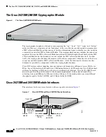
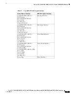
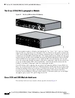
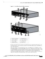
The Cisco 1721, 1760, 2621XM, 2651XM, 2691, 3725, 3745, and 7206 VXR NPE-400 Routers
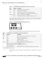
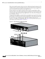
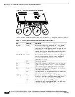
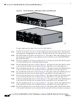
Figure 17
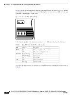
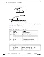
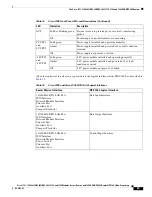
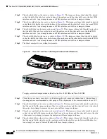
Cisco 3725 and Cisco 3745 Front Panel LEDs
Figure 17
shows the front panel LEDs, which provide overall status of the router's operation. The front
panel displays whether or not the router is booted, if the redundant power is (successfully) attached and
operational, and overall activity/link status.
Table 13
and
Table 14
provide more detailed information conveyed by the LEDs on the front panel of
the routers:
SYS LED
ACT LED
SYS PS1 LED
-48V PS1 LED
-48 PS2 LED
SYS PS2 LED
PWR LED
SYS/RPS LED
ACT LED
PWR
SYS
RPS
ACT
99507
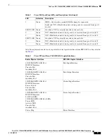
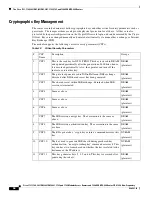
Table 13
Cisco 3725 Front Panel LEDs and Descriptions
LED
Indication
Description
PWR
Solid green
Router is receiving power
Off
Router is not receiving power
SYS/RPS
Solid green
System is operating normally
Rapid blinking
System is booting up or in ROM monitor mode
Blinking once per second
Redundant power system has failed
Off
Router is not receiving power
ACT
Blinking
System is actively transferring packets
Off
No packet transfers are occurring
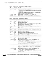
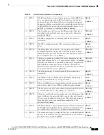
Table 14
Cisco 3745 Front Panel LEDs and Descriptions
LED
Indication
Description
SYS
Solid green
System is operating normally
Blinking green
Running ROM monitor with no errors detected
Amber
Router is receiving power but malfunctioning
Off
Router is not receiving power


