


12
Cisco 1721, 1760, 2621XM, 2651XM, 2691, 3725, and 3745 Modular Access Routers and 7206-VXR NPE-400 Router FIPS 140-2 Non-Proprietary
OL-6083-01
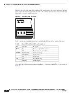
The Cisco 1721, 1760, 2621XM, 2651XM, 2691, 3725, 3745, and 7206 VXR NPE-400 Routers
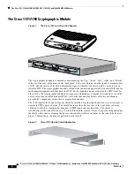
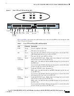
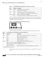
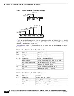
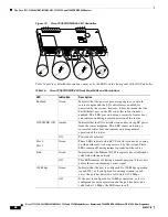
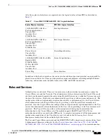
Figure 9
shows the front panel LEDs, which provide overall status of the router's operation. The front
panel displays whether or not the router is booted, if the redundant power is (successfully) attached and
operational, and overall activity/link status.
Figure 9
Cisco 2621XM and Cisco 2651XM Front Panel LEDs
Table 6
provides more detailed information conveyed by the LEDs on the front panel of the router:
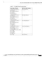
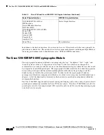
All of these physical interfaces are separated into the logical interfaces from FIPS 140-2 as described in
Table 7
:
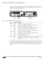
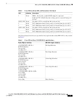
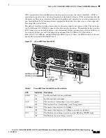
Table 5
Cisco 2621XM and Cisco 2651XM Rear Panel LEDs and Descriptions
LED
Indication
Description
LINK
Green
An Ethernet link has been established
Off
No Ethernet link established
FDX
Green
The interface is transmitting data in full-duplex mode
Off
When off, the interface is transmitting data in half-duplex mode
100 Mbps
Green
The speed of the interface is 100 Mbps
Off
The speed of the interface is 10 Mbps or no link is established
POWER
RPS
ACTIVITY
99496
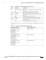
Table 6
Cisco 2621XM and Cisco 2651XM Front Panel LEDs and Descriptions
LED
Indication
Description
Power
Green
Power is supplied to the router and the router is operational
Off
The router is not powered on
RPS
1
1. RPS = Redundant Power System
Green
RPS is attached and operational
Off
No RPS is attached
Blink
RPS is attached, but has a failure
Activity
Off
In the Cisco IOS software, but no network activity
Blink (500 ms ON, 500 ms OFF) In ROMMON, no errors
Blink (500 ms ON, 500 ms OFF,
2 sec between codes)
In ROMMON, error detected
Blink (less than 500 ms)
In the Cisco IOS software, the blink rate reflects the level of activity


