background image

ETC Setup Guide

Response SMPTE Gateway

Corporate Headquarters Middleton, WI, USA +1 608 831 4116 London, UK +44 (0)20 8896 1000

Holzkirchen, DE +49 (80 24) 47 00-0 Rome, IT +39 (06) 32 111 683 Hong Kong +852 2799 1220 Paris, FR +33 1 4243 3535

Web


etcconnect.com

 Support 

support.etcconnect.com 

Contact 

etcconnect.com/contactETC

© 2019 Electronic Theatre Controls, Inc. Trademark and patent info: 

etcconnect.com/ip 

Product information and specifications subject to change. ETC intends this document to be provided in its entirety.

4267M2270 Rev B Released 2019-11

Overview

The Response SMPTE Gateway allows you to receive a SMPTE control signal from an external source and 
then pass it through to your lighting network or console, providing a simple way to synchronize other 
systems with your lighting control. The SMPTE signal is generated by the controlling device and transmitted 
to the SMPTE Gateway. The gateway acts as a receiver in a SMPTE system.

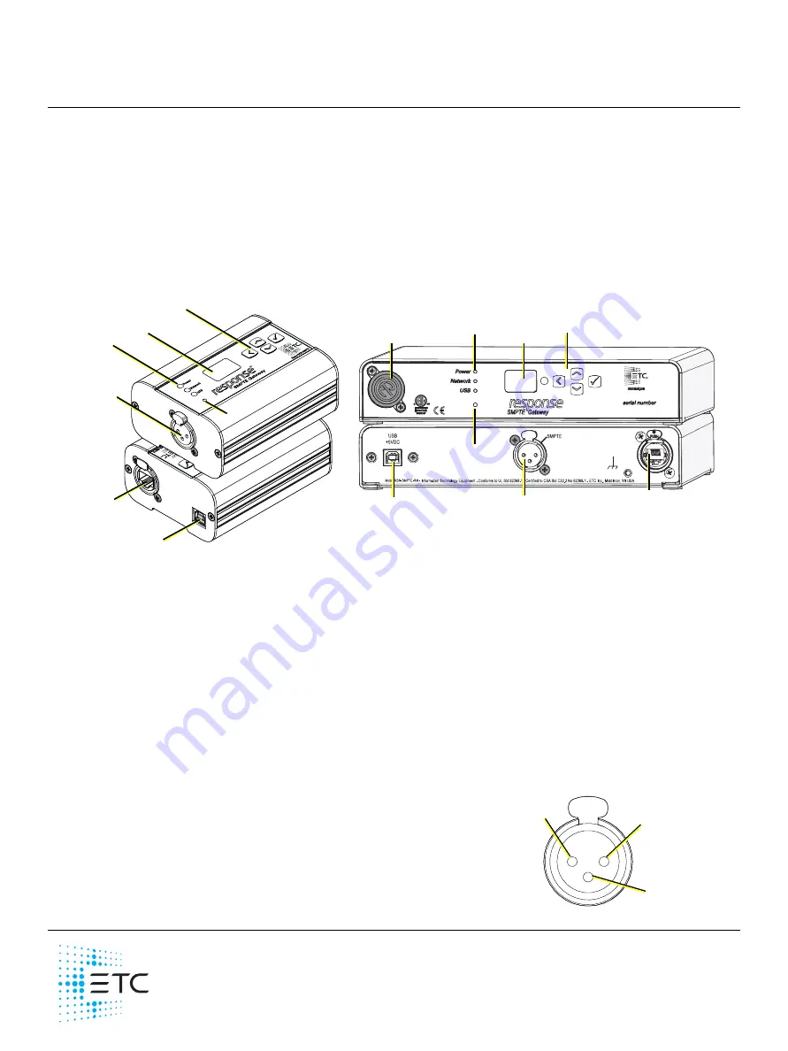
There is a backpack and rack-mounted version of the SMPTE gateway.

LED Indicators

• Power - solid blue indicates that power is supplied
• Network - solid green indicates network connection and blinking indicates network activity
• USB - solid green indicates USB connection and solid red indicates connection without having fully 

detected, identified and loaded device drivers

Action Buttons

• Up, Down, Back buttons - The Back button allows you to return to the previous menu option and the 

Up and Down buttons navigate between menu options

• Enter - The Enter button allows you to advance to the next available menu option or commit a 

modified selection

• Reset - The Reset button provides a physical button to reset the gateway but does not restore factory 

settings

SMPTE Connection

The three-pin XLR connector on the gateway allows for connection 
of an LTC SMPTE source in the form of a balanced audio input.

SMPTE 
Input

Up, Down, Back, 
Enter buttons

LED 
indicators

OLED 
screen

Res

et 

but

ton

SMPTE Input

Reset button

LED 
indicators

OLED 
screen

Up, Down, Back, 
Enter buttons

Ethernet 
port

USB port

USB port

Ethernet 
port

Alternative 
Ethernet location

Rack Mount version

Backpack version

1

2

3

In Phase
()

Out of phase
(Signal -)

Common
(Ground)

Summary of Contents for Response SMPTE

Page 1: ...ion of the SMPTE gateway LED Indicators Power solid blue indicates that power is supplied Network solid green indicates network connection and blinking indicates network activity USB solid green indicates USB connection and solid red indicates connection without having fully detected identified and loaded device drivers Action Buttons Up Down Back buttons The Back button allows you to return to th...

Page 2: ...n this scenario the USB connection must be made directly to the lighting console Switching the Network Port Rack Mount Only The rack mount variant of the SMPTE gateway can have the Ethernet connector installed on the front or back of the unit To switch the location perform the following steps 1 Using a Phillips screwdriver remove the four screws on the bottom of the gateway and slide the cover off...

Page 3: ...ings is set to the same ID as the Source ID entered in your Event List Using SMPTE in Eos Event Lists You can trigger events in Eos from SMPTE using Show Control Event Lists For additional information on event lists in Eos refer to the Eos Family Operations Manual 1 On your console navigate to the Show Control tab and create a list 2 In the Type field enter SMPTE 3 In the Source field For SMPTE ov...

Page 4: ...nual you must configure the IP Address IP Subnet and IP Gateway screens and then select OK from the Apply Reboot screen If you select Link Local you can have the addressing done using your system s link local addressing mechanism Select OK from the Apply Reboot screen If your network settings are not valid after configuration a warning appears for 3 seconds and then you are returned to the Mode sc...

Page 5: ...gateways for mounting into a standard 19 rack enclosure If you only need to mount one unit a blanking plate is provided with the kit This blanking plate can be installed on either side of the rack mount bracket Hanging Hardware Kit 4260K1005 The Hanging Hardware Kit allows pipe mounting of a gateway in a variety of orientations You can vary the way the U bolt or c clamp attaches to the bracket and...

Reviews: