


9
Cisco 1721, 1760, 2621XM, 2651XM, 2691, 3725, and 3745 Modular Access Routers and 7206-VXR NPE-400 Router FIPS 140-2 Non-Proprietary
OL-6083-01
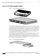
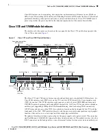
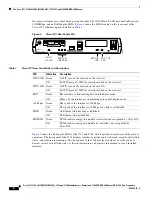
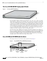
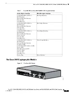
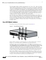
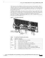
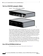
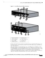
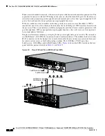
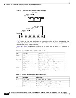
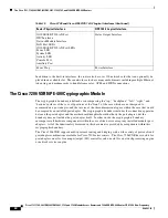
The Cisco 1721, 1760, 2621XM, 2651XM, 2691, 3725, 3745, and 7206 VXR NPE-400 Routers
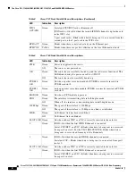
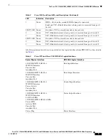
All of these physical interfaces are separated into the logical interfaces from FIPS 140-2 as described in
the
Table 4
:
1
Green
ISDN—On when the second ISDN B channel is connected
Serial and VIC—Blinks when data is being sent to or received from port 1
in slot 1
SLOT 2 OK Green
On when a VIC is correctly inserted in the card slot
0
Green
VIC—Blinks when data is being sent to or received from port 0 in slot 2
1
Green
VIC—Blinks when data is being sent to or received from port 1 in slot 2
SLOT 3 OK Green
On when a VIC is correctly inserted in the card slot
0
Green
VIC—Blinks when data is being sent to or received from port 0 in slot 3
1
Green
VIC—Blinks when data is being sent to or received from port 1 in slot 3
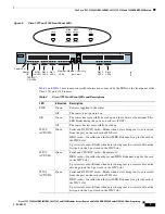
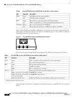
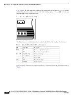
Table 3
Cisco 1760 Front Panel LEDs and Descriptions (Continued)
LED
Indication
Description
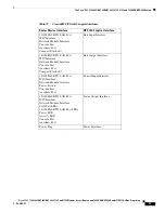
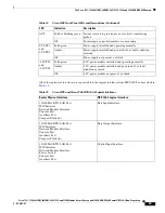
Table 4
Cisco 1721 and Cisco 1760 FIPS 140-2 Logical Interfaces
Router Physical Interface
FIPS 140-2 Logical Interface
10/100BASE-TX LAN Port
WIC/VIC Interface
Console Port
Auxiliary Port
Data Input Interface
10/100BASE-TX LAN Port
WIC/VIC Interface
Console Port
Auxiliary Port
Data Output Interface
10/100BASE-TX LAN Port
WIC/VIC Interface
Power Switch
Console Port
Auxiliary Port
Control Input Interface
10/100BASE-TX LAN Port
WIC/VIC Interface
LAN Port LEDs
10/100BASE-TX LAN Port LEDs
Power LED
Activity LED
Console Port
Auxiliary Port
Status Output Interface
Power Plug
Power Interface


