C I R R U S
C O M P O N E N T M A I N T E N A N C E M A N U A L - C A P S
M O D E L S R 2 0
95-01-01
Page 51
Serials 1625 thru 2227, 1625 thru 2227 w/o Perspec-
tive before SB2X-95-18
EFFECTIVITY:
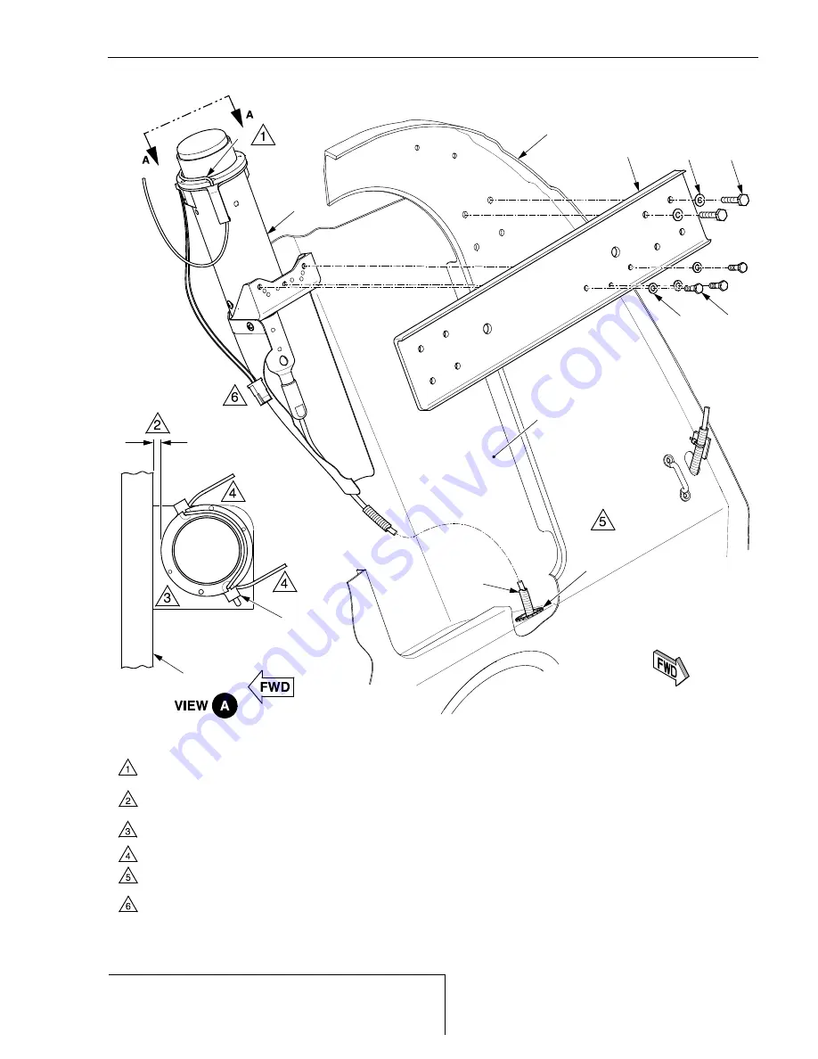
Figure 95-01-0111
Rocket Installation - Serials 1625 thru 2227, 1625 thru 2227 w/o Perspective before SB2X-95-18 (7 of 10)
6
5
To facilitate rocket assembly removal, move CAPS harness to either side and carefully
pull spiral wrap cable from adjustable bushing pass-through hole as required.
BH 222
(REF)
CAPS COMPARTMENT
(REF)
LEGEND
1. Bolt
2. Washer
5. Rocket Assembly
6. Rocket Lanyard
8. Spiral Wrap
20. Cross Beam
8
SR20_CM95_2628C
1
20
2
2
1
ADJUSTABLE
BUSHING
(REF)
0.40 inch
(10.16 mm)
BH 222
(REF)
PICK-UP
COLLAR
(REF)
Ensure ends of lanyard routed aft do not wrap around forward portion of rocket assembly.
Position rocket lanyard around top outer diameter of pick-up collar support,
NOT over top of the rocket. Failure to comply will absolutely FAIL rocket deployment!
NOTE
Incorrect gap between outer diameter of pick-up collar and aft side of BH 222 may result in
deployment failure.
Serials 1886 & subs w/ Aircraft Data Logger:
Connect plug P1046 to jack J1046 and secure
wire harness with cable ties to existing cable anchors on rocket shield.
Verify LH edge of pick-up collar is oriented away from BH 222.
Serials 1625 thru 2227,
1625 thru 2227 w/o Perspective before SB2X-95-18.
4 May 2015


