C I R R U S
C O M P O N E N T M A I N T E N A N C E M A N U A L - C A P S
M O D E L S R 2 0
95-01-01
Page 47
Serials 1005 thru 1267 after SB2X-95-20, 1268 thru
1422 after SB2X-95-17
EFFECTIVITY:
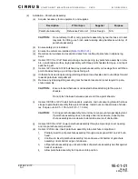
Figure 95-01-0111
Rocket Installation - Serials 1005 thru 1267 after SB2X-95-20, 1268 thru 1422 after SB2X-95-17 (3 of 10)
6
5
A1
A1
1
PICK-UP
COLLAR
(REF)
0.13 inch
(3.30 mm)
BH 222
(REF)
2
3
2
3
55
4
2
2
Ensure ends of lanyard routed aft do not wrap around forward portion of rocket assembly.
Position rocket lanyard around top outer diameter of pick-up collar support,
NOT over top of the rocket. Failure to comply will absolutely FAIL rocket deployment!
ADJUSTABLE
BUSHING
(REF)
Washers as required to achieve correct gap between pick-up collar and BH 222. Failure
to do so may result in an incorrect rocket installation and subsequent deployment failure.
NOTE
Incorrect gap between outer diameter of pick-up collar and aft side of BH 222 may result in
deployment failure.
To facilitate rocket assembly removal, move CAPS harness to either side and carefully
pull spiral wrap cable from adjustable bushing pass-through hole as required.
BH 222
(REF)
LEGEND
1. Bolt
2. Washer
3. Backing Plate
5. Rocket Assembly
6. Rocket Lanyard
8. Spiral Wrap
SR20_CM95_3604
1
2
3
8
Serials 1005 thru 1267 after SB2X-95-20, 1268 thru 1422 after SB2X-95-17.
Verify LH edge of pick-up collar is oriented away from BH 222.
4 May 2015


