DIAGNOSTICS
Page 33 of 36
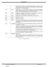
belt for belt rip condition. N/O or N/C status selected in Mode DIP switch
settings. LED is Green when output is on. Latching output
– resets by Reset
pushbutton or via communications.
DO4
Green
Digital output
–Fault output to PLC. Triggers for device fault, sensor beam
failure or Reset forced conditions. LED is Green when output is on. Latching
output
– resets by Reset pushbutton or via communications.
DI0
Green
Digital Input
– Receiver sensor input. On when beam is received from
emitter (signal healthy). LED is Green when input is on.
DI1
Green
Digital Input
– Reset pushbutton. LED is Green when input is on.
DI2
Green
Digital Input
– Spare
DI3
Green
Digital Input
– Spare
ETH
Green
The Ethernet LED will light up when an Ethernet link has been detected (by
plugging in a connected Ethernet cable). The LED will flash every time traffic
was detected.
OK
Green/Red The module LED will provide information regarding the system-level
operation of the module.
If the LED is red, then the module is not operating correctly. For example, if
the module application firmware has been corrupted or there is a hardware
fault the module will have a red Module LED.
If the LED is green (flashing), then the module has booted and is running
correctly without any application configuration loaded.
If the LED is green (solid), then the module has booted and is running
correctly with application configuration loaded.
STS
Green/Red Status LED
When in Modbus-TCP mode, the LED flashes green every time a valid
Modbus request is received and flashes red every time an invalid Modbus
request is received.
Table 6.1
–
Diagnostic LED’s


