


INSTALLATION
Page 13 of 36
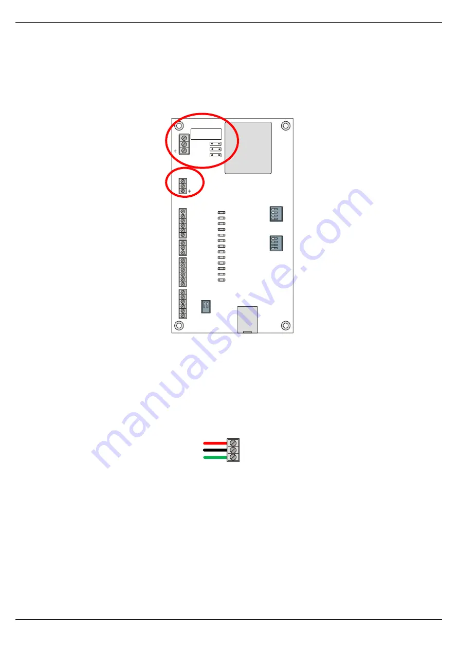
2.3. POWER
Each unit is equipped with both a 24VDC input as well as an AC input (either 110VAC
or 220VAC).
Only one of the two options is required to be connected.
1
2
1
3
2
4
1
3
2
4
PWR
+24V
+24V
+24V
+24V
+24V
+24V
+24V
+24V
DO0
0V
DO1
DO2
C34
DO3
DO4
DI0
DI1
DI2
DI3
COM
AI+
0V
DO0
DO1
DO2
DO3
DO4
DI0
DI1
M
O
D
E
S
Y
S
T
E
M
DI2
DI3
ETH
OK
STS
TRANSFORMER
ETHERNET
SW-3
J
5
J
3
J
2
1
2
1
3
2
4
1
3
2
4
PWR
+24V
+24V
Live
+24V
+24V
+24V
+24V
+24V
+24V
DO0
0V
Neut
DO1
DO2
C34
DO3
DO4
DI0
DI1
DI2
DI3
COM
AI+
0V
DO0
DO1
DO2
DO3
DO4
DI0
DI1
M
O
D
E
S
Y
S
T
E
M
DI2
DI3
ETH
OK
STS
TRANSFORMER
ETHERNET
SW-3
J
5
J
3
J
2
Fuse F1
AC POWER
DC POWER
Figure 2.9
–
AC & DC Power Circuits
2.3.1.
DC
I
NPUT
A three-way power connector is used to connect Power+, Power
– (ground), and earth.
The module requires an input voltage of 24VDC. Refer to the technical specifications
section in this document.
+24V
0V
Earth
Figure 2.10
–
DC Power Connector


