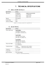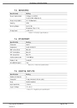
MODBUS TCP MAPPING
Page 31 of 36
5.1.1. M
ONITOR
D
ISCRETE
I
NPUTS
Type
Address
Description
Type
Count
DI
0
General Status - Bit 0 - Class 1 owned
BOOL
1
DI
1
General Status - Bit 1
– Modbus Comms OK
BOOL
1
DI
2
General Status - Bit 2
– Sensor Beam Healthy
BOOL
1
DI
3
General Status - Bit 3 - Trip
BOOL
1
DI
4
General Status - Bit 4 - Fault
BOOL
1
DI
5
General Status - Bit 5
– BeamTestFail
BOOL
1
DI
6
General Status - Bit 6
– Reset Tamper
BOOL
1
DI
7
General Status - Bit 7
– Reset Button
BOOL
1
DI
8
General Status - Bit 7
– Beam Self-Test Enabled
BOOL
1
DI
16
DI Status - DI0
BOOL
1
DI
17
DI Status
– DI1
BOOL
1
DI
18
DI Status
– DI2
BOOL
1
DI
19
DI Status
– DI3
BOOL
1
DI
24
DO Status - DO0
BOOL
1
DI
25
DO Status
– DO1
BOOL
1
DI
26
DO Status
– DO2
BOOL
1
DI
27
DO Status
– DO3
BOOL
1
DI
28
DO Status
– DO4
BOOL
1
Table 5.2
–
Modbus TCP Discrete Inputs
5.1.1. C
ONTROL
O
UTPUTS
Type
Address
R/W
Description
Type
Count
Comment
HR
100
R/W
ResetStatsCommand
INT
1
Transition from 0-1
triggers reset status
HR
101
R/W
Reserved
INT
1
HR
102
R/W
Reserved
INT
1
HR
103
R/W
Reserved
INT
1
Table 5.3
–
Modbus TCP Control


