


LOGIX MAPPING
Page 27 of 36
4. LOGIX MAPPING
The Belt Rip and Tear module can be added in the Logix IO tree to provide diagnostics
information to the Logix controller. The Logix controller will establish a class 1 cyclic
communication connection with the module. An input and output assembly is
exchanged at a fix interval.
As described in chapter 3, by co
pying the module’s input assembly to the supplied
UDT, the following structured parameters can be extracted:
4.1.1.
I
NPUT
A
SSEMBLY
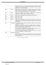
The following parameters are used in the input assembly of the Belt Rip and Tear
module.
Parameter
Datatype Description
Instance
STRING
The instance name of the module that was
configured under the general Belt Rip and Tear
module configuration in Circular Configurator.
Input
General Status
BOOL
Bit 0 - Class 1 owned
Bit 1 - Modbus comms OK
Bit 2 - Sensor Beam Healthy
Bit 3 - Trip
Bit 4
– Fault
Bit 5
– Beam Test Fail
Bit 6
– Reset Button Tamper
Bit 7
– Reset Button
Bit 8
– Beam Self-Test Enabled
Mode DIP Switch
SINT
Status of Mode DIP-Switches
System DIP Switch Boot
SINT
Status of System DIP-Switches at power-up
System DIP Switch Current
SINT
Status of System DIP-Switches
Firmware Major Rev
SINT
Major Firmware Revision
Firmware Minor Rev
SINT
Minor Firmware Revision
Firmware Micro Rev
SINT
Micro Firmware Revision
DI Status
SINT
Status of input DI0 to DI3
DO Status
SINT
Status of outputs DO0-DO4
CPU Temperature
REAL
CPU temperature (°C)
UpTime
DINT
Seconds since power-up


