DIAGNOSTICS
Page 32 of 36
6. DIAGNOSTICS
6.1. LEDS
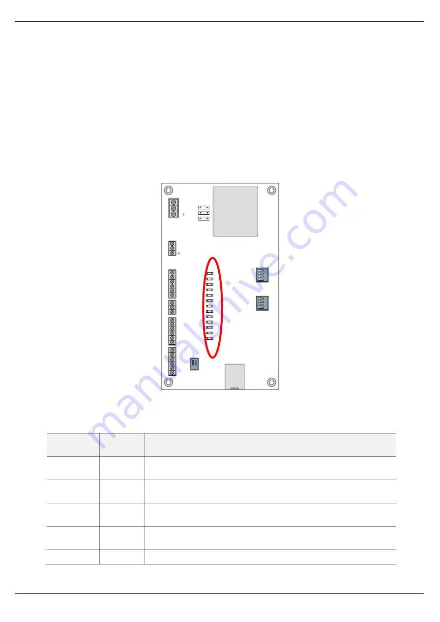
The module PCB is equipped with multiple diagnostic LEDs as shown in Figure 6.1 -
Module Diagnostic LEDs. These LEDs are used to provide information regarding the
modules system operation, power supply, the Ethernet interface as well as the status
of the inputs and outputs.
1
2
1
3
2
4
1
3
2
4
PWR
+24V
+24V
Live
+24V
+24V
+24V
+24V
+24V
+24V
DO0
0V
Neut
DO1
DO2
C34
DO3
DO4
DI0
DI1
DI2
DI3
COM
AI+
0V
DO0
DO1
DO2
DO3
DO4
DI0
DI1
M
O
D
E
S
Y
S
T
E
M
DI2
DI3
ETH
OK
STS
TRANSFORMER
ETHERNET
SW-3
J
5
J
3
J
2
Figure 6.1 - Module Diagnostic LEDs
LED
Description
Colour
Description
PWR
Green
Indicates that the unit is powered
– either from the 24VDC supply or
alternately from the 110/220V AC supply.
DO0
Green
Digital Output
– used to power Sensor Healthy LED. LED is Green when
output is on.
DO1
Green
Digital Output
– used to power Trip/Fault LED. LED is Green when output
is on.
DO2
Green
Digital Output
– used to for the Emitter Gate. LED is Green when output is
on.
DO3
Green
Digital Output
– Trip output to PLC or control circuit. Used to trip conveyor


