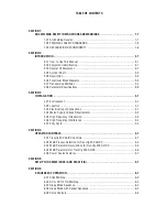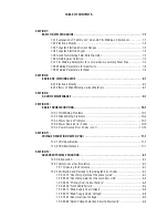
TABLE OF CONTENTS
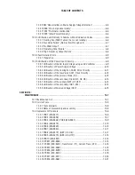
12.2.9 E83 "Abnormalities in Mains Supply Voltage Detection" ...................... 6-5
12.2.10 E85 "Pre-charge abnormality" ............................................................ 6-6
12.2.11 E94 "Thermistor malfunction" ............................................................ 6-6
12.2.12 E99 "Initial Power Receiving" ............................................................. 6-6
12.03 Verification and Remedy to Failures without Indication Codes ..................... 6-6
12.3.1 "Cooling Fan (FAN1) Failure" (Fan is not rotating.) ............................... 6-6
12.3.2 "Gas Valve Failure" (No Gas flow through unit) .................................... 6-7
12.3.3 "No Weld Output" ................................................................................. 6-7
12.3.4 "Operating Panel Failure" ...................................................................... 6-8
12.3.5 "High Frequency Output Failure" .......................................................... 6-8
12.04 Fault Isolation Tests ...................................................................................... 6-9
12.4.1 Preparation .......................................................................................... 6-9
12.05 Verification of the Power Input Circuitry ....................................................... 6-9
12.5.1 Verification of the AC Input Voltage using an AC Voltmeter ................. 6-9
12.5.2 Verification of Power Supply Voltage ................................................. 6-10
12.5.3 Verification of the Cooling Fan, FAN1, Drive Circuitry ........................ 6-11
12.5.4 Verification of the Gas Valve, SOL1, Drive Circuitry ........................... 6-12
12.5.5 Verification of the primary Diode (D1) ............................................... 6-12
12.5.6 Verification of the secondary Diode (D2, D4, D5) .............................. 6-13
12.5.7 Verification of the primary IGBT (Q1-Q12) ........................................ 6-14
12.5.8 Verification of the secondary IGBT (Q13) .......................................... 6-14
12.5.9 Verification of No-load Voltage (OCV) ............................................... 6-15
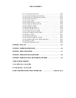
SECTION 13:
MAINTENANCE ...................................................................................... 13-1
13.1 Maintenance List .......................................................................................... 13-1
13.2 Service Tools ................................................................................................ 13-5
13.2.1 Tools and parts .................................................................................. 13-5
13.2.2 Notes of disassembly and assembly ................................................. 13-5
13.3 Replacement Procedure ............................................................................... 13-6
13.3.1 PCB1 (WK-5477) ............................................................................... 13-6
13.3.2 PCB2 (WK-5596) ............................................................................... 13-7
13.3.3 PCB3 (WK-5548), PCB5 (WK-5551) ................................................. 13-9
13.3.4 PCB4 (WK-4819) ............................................................................. 13-10
13.3.5 PCB6 (WK-5549) ............................................................................. 13-10
13.3.6 PCB7 (WK-5550) ............................................................................. 13-11
13.3.7 PCB8 (WK-5479) (IGBT (Q1~Q6)) ................................................... 13-11
13.3.8 PCB9 (WK-5479) (IGBT (Q7~Q12)) ................................................. 13-12
13.3.9 PCB10 (WK-5527) ........................................................................... 13-13
13.3.10 PCB11 (WK-5528) ......................................................................... 13-13
13.3.11 PCB12 (WK-5615), Transformer (T1), Current Trans (CT2) .......... 13-15
13.3.12 PCB13 (WK-5569) ......................................................................... 13-18
13.3.13 PCB16 (WK-5499) ......................................................................... 13-19
13.3.14 PCB14 (WK-5570) ......................................................................... 13-19
13.3.15 PCB17 (WK-4917) ......................................................................... 13-20
13.3.16 PCB18 (WK-5861) ......................................................................... 13-21
Summary of Contents for TRANSTIG 200 AC/DC
Page 8: ...THIS PAGE LEFT INTENTIONALLY BLANK ...
Page 20: ...TRANSTIG 200 AC DC SERVICE MANUAL 2 6 January 17 2008 NOTES ...
Page 34: ...5 2 January 17 2008 TRANSTIG 200 AC DC SERVICE MANUAL NOTES ...
Page 58: ...January 17 2008 11 2 TRANSTIG 200 AC DC SERVICE MANUAL NOTES ...
Page 74: ...TRANSTIG 200 AC DC SERVICE MANUAL January 17 2008 12 16 THIS PAGE LEFT INTENTIONALLY BLANK ...
Page 111: ...THIS PAGE LEFT INTENTIONALLY BLANK SERVICE MANUAL TRANSTIG 200 AC DC January 17 2008 13 37 ...
Page 122: ...A 11 January 17 2008 TRANSTIG 200 AC DC SERVICE MANUAL NOTES ...
Page 126: ......


