SERVICE MANUAL
TRANSTIG 200 AC/DC
January 17, 2008
12-11
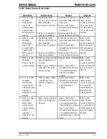
TP1
TP2
TP3
TP0
PCB6
Figure 6-10: Checkpoints TP0-TP3 on PCB6
Check Point
Reference
ACCEPTABLE
PCB3
PCB3
VALUE
Pin 1 on CN18 Pin 3 on CN18
+24VDC
Table 6-1: Checkpoints TP0-TP3 on PCB6
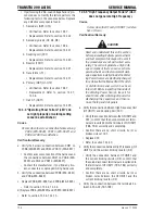
PCB3
CN18
pin 1
pin 3
Figure 6-11: Checkpoints CN18 on PCB3
3. If any of these voltages are not present or are be-
low a 10% tolerance, replace PCB3 (WK-5548).
Refer to section 13.3.4.
12.5.3 Verification of the Cooling Fan, FAN1,
Drive Circuitry
CAUTION
Before performing any portion of the pro-
cedure below, make certain the unit is
placed in the initial set up condition as
described in section 12. 4.1 "Preparation".
1. Verify the condition of the cooling fan, FAN1, us-
ing a DC voltmeter. (The capability of the voltme-
ter should be more than 50VDC.) Using a DC volt-
meter, measure between PIN 1 (Positive [+]) and
PIN 2 (Negative [-]) of CN11 on PCB3 (WK-5548).
The location of connector CN11 of PCB3 is indi-
cated in Figure 6-12. When you measure the above
voltage, do not remove the connector. Conduct
the measurement while the connector plug and
receptacle are still connected.
PCB3
CN11
1pin
2pin
Figure 6-12: Verification of the FAN1
2. Using the measurement taken above, follow the
chart below for possible failure modes.
FAN1
Status
Voltage
measurement.
(1PIN-2PIN of
CN11 on PCB3)
Remedy
Case
1
Rotating
DC 18 ~ 25V
FAN1 drive circuit is
normal.
Case
2
Rotating Below
DC
18V
Replace PCB3. Refer
to section 12.3.4.
Case
3
Inactive Below
DC
18V
Replace PCB3. Refer
to section 12.3.4.4.
Perform “2".
Verfication of Power
Supply Voltage” Refer
to section 11.5.2.
Case
4
Inactive
DC 18 ~ 25V
Replace the FAN1.
Refer to section
12.3.24.
Table 6-3: Verification of the FAN1
Summary of Contents for TRANSTIG 200 AC/DC
Page 8: ...THIS PAGE LEFT INTENTIONALLY BLANK ...
Page 20: ...TRANSTIG 200 AC DC SERVICE MANUAL 2 6 January 17 2008 NOTES ...
Page 34: ...5 2 January 17 2008 TRANSTIG 200 AC DC SERVICE MANUAL NOTES ...
Page 58: ...January 17 2008 11 2 TRANSTIG 200 AC DC SERVICE MANUAL NOTES ...
Page 74: ...TRANSTIG 200 AC DC SERVICE MANUAL January 17 2008 12 16 THIS PAGE LEFT INTENTIONALLY BLANK ...
Page 111: ...THIS PAGE LEFT INTENTIONALLY BLANK SERVICE MANUAL TRANSTIG 200 AC DC January 17 2008 13 37 ...
Page 122: ...A 11 January 17 2008 TRANSTIG 200 AC DC SERVICE MANUAL NOTES ...
Page 126: ......

