SERVICE MANUAL
TRANSTIG 200 AC/DC
January 17, 2008
12-1
SECTION 12:
ADVANCED TROUBLE SHOOTING
12.00 Introduction
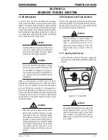
If you are here, all of the troubleshooting sugges-
tions in Section 5 Basic Troubleshooting have either
failed to resolve the faulty operation or have indicated
that one or more of the subsystems within the power
supply are defective. This section provides the infor-
mation needed to take live measurements on the vari-
ous subsystems within the power supply, and replace
those subsystems that prove faulty.
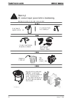
CAUTION
Troubleshooting and repairing this unit is
a process, which should be undertaken
only by those familiar with high voltage/
high power electronic equipment.
!
WARNING
There are extremely dangerous voltage
and power levels present inside this unit.
Do not attempt to diagnose or repair un-
less you have training in power electron-
ics, measurement and troubleshooting
techniques.
Under no circumstances are field repairs to be at-
tempted on printed circuit boards or other subassem-
blies of this unit. Evidence of unauthorized repairs
will void the factory warranty. If a subassembly is
found to be defective by executing any of the proce-
dures in this Service Manual, the subassembly should
be replaced with a new one. The faulty subassembly
should then be returned to Cigweld through estab-
lished procedures.
!
WARNING
Disconnect primary power at the source
before disassembling the power supply.
Frequently review the "Important Safety
Precautions" in section 1.02. Be sure the
operator is equipped with proper gloves,
clothing and eye and ear protection. Make
sure no part of the operator's body comes
into contact with the work piece or any
internal components while the unit is ac-
tivated.
12.01 System-Level Fault Isolation
If none of the suggestions provided in Section 5 have
solved the problem or corrected the faulty operation,
the next step is to isolate one or more of the internal
subassemblies that may be defective.
CAUTION
Perform all steps in each procedure, in
sequence. Skipping portions of proce-
dures, or performing steps out of se-
quence can result in damage to the unit,
and possible injury, or worse, to the op-
erator.
12.1.1 Opening the Enclosure
1. Confirm that the switch on the power supply and
the switch on switchboard (distribution panel) are
all OFF.
Figure 12-1: Switch OFF
CAUTION
The capacitors inside the power supply will
slowly discharged after you turn off the
switch of the power supply or the switch
at the breaker box (distribution panel).
Wait at least 5 minutes for the discharge
to complete.
Summary of Contents for TRANSTIG 200 AC/DC
Page 8: ...THIS PAGE LEFT INTENTIONALLY BLANK ...
Page 20: ...TRANSTIG 200 AC DC SERVICE MANUAL 2 6 January 17 2008 NOTES ...
Page 34: ...5 2 January 17 2008 TRANSTIG 200 AC DC SERVICE MANUAL NOTES ...
Page 58: ...January 17 2008 11 2 TRANSTIG 200 AC DC SERVICE MANUAL NOTES ...
Page 74: ...TRANSTIG 200 AC DC SERVICE MANUAL January 17 2008 12 16 THIS PAGE LEFT INTENTIONALLY BLANK ...
Page 111: ...THIS PAGE LEFT INTENTIONALLY BLANK SERVICE MANUAL TRANSTIG 200 AC DC January 17 2008 13 37 ...
Page 122: ...A 11 January 17 2008 TRANSTIG 200 AC DC SERVICE MANUAL NOTES ...
Page 126: ......


