Chrysler IIIH Assembly Manual Download Page 28

All operators should become familiar with the Sunnen SV‐10 Hone Operator Manual, safety precautions,  
set up procedures, and operations of the SV‐10 Hone before honing engine blocks.  

Required Parts and Equipment

1.


Sunnen SV‐10 Hone Machine

2.


Sunnen Honing Oil SHO965055 (55 gal.) / SHO965005 (5 gal.)

3.


Course Diamond Stones:  Sunnen DHH6GMH85

4.


Plateau Brush:  Sunnen DHHB6534 (DHHB7534 is an adequate substitute)

5 Sunnen Bore Gauge;

G

A

M‐2121

12" depth, 0.002mm resolution indicator dial bore gauge.

G

R

M‐2121

12" depth, 0.002mm resolution, with retractable indicator dial bore gauge.

G

A

M‐2121E 12" depth, 0.002mm resolution indicator bore gauge with digital readout. 

G

R

M‐2121E 12" depth, 0.002mm resolution retractable indicator bore gauge with digital readout.

Machine Setup

Place the block in the SV‐10 honing machine with the front of the block facing left.
Set the stroke length to 3.0 " on the inch scale or 75 mm on the metric scale.
Set the Ratchet Feed setting to 1.
Manually set the tilting table height to 3/8" or 9.65mm.

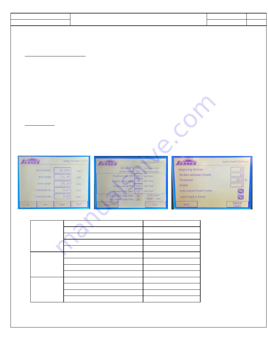
Using the automated setup screens input the following parameters;

Bore Diameter

95.90mm

Bore Length

131.76mm

Stone Length

76.20mm

Over stroke Top

9.65mm

Over stroke Bottom

9.65mm

Roughing Spindle Speed RPM

200

Roughing Stroke Speed

80

Finishing Spindle Speed RPM

200

Finishing Stroke Speed

80

Beginning Strokes

10

Strokes Between Dwells

10

Threshold

20%

Dwells

2

These user input values should yield an average X‐hatch angle of 36° and a stroke length of 74.9 mm.

Section

4

Mar‐16

Sheet

8

Auto Dwell

Settings

Screen 1

Screen 2

Sunnen SV‐10

IIIH Hone Settings

Revision DRAFT

Summary of Contents for IIIH

Page 1: ...Jeff Betz 313 363 8093 Fiat Chrysler America This document is to be used as a supplement to the Chrysler Sequence IIIH Engine Oil Certification Test ASTM Standard Test Method D and is used in conjunct...

Page 2: ...Core Preparation 3 New Engine Disassembly 4 Main Oil Gallery Modifications and Honing 5 Post Honing and Special Parts Cleaning 6 Cylinder Head Pre Build Cleaning and Assembly 7 Short Block Assembly an...

Page 3: ...Assembly Piston Ring Width Top Second Oil Control Rails Description Specification 60 DOHC V 6 24 Valve Chrysler IIIH Engine Specifications Revision 1 June 18 Section Sheet 1 1 10 2 1 1 Right Bank 1 2...

Page 4: ...237 in 0 023 0 061 mm 0 0009 0 0024 in 44 75 0 25 from the valve guide axis 0 030 0 068 mm 0 0012 0 0027 in 1 0 1 2 mm 0 04 0 05 in 1 41 1 61 mm 0 055 0 063 in Metric Standard 0 48 0 60 mm 0 019 0 024...

Page 5: ...ing Cover M6 Bolt Coolant Pump Plate to Engine Timing Cover M10 Bolt Crankshaft Target Wheel to Counterweight M6 T30 Crankshaft Outer Main Bearing Cap and Windage Tray M8 Bolt Crankshaft Inner main Be...

Page 6: ...5 Oil Pump Pickup Tube Bracket to Windage Tray M6 Bolt Oil Pump Pickup Tube to Oil Pump M6 Bolt Oil Level Indicator to Cylinder Head M6 Bolt Oil Pump Sprocket M8 T45 17 151 25 18 12 106 12 106 Oil Pum...

Page 7: ...uire a scratch free sealing surface Valve to Piston interference will occur if not properly disassembled assembled Remove all gasket materials from cylinder head and block using care not to gouge or s...

Page 8: ...1 Sheet 2 June 18 Remove all valvetrain hardware from cylinder heads camshafts roller rockers lash adjusters valve springs valve seals and spark plugs Camshaft caps are identified on the sides 1E 2E e...

Page 9: ...Section 3 New Engine Disassembly...

Page 10: ...aged for shipment to IMTS for special processing Packaging from the new cylinder heads to be used for the test should be used for return of new core materials to IMTS Remove the flywheel and disengage...

Page 11: ...wer intake manifold is an injection molded nylon composite design The lower intake seals to the cylinder heads using six individual silicone gaskets The seven upper intake manifold fasteners thread di...

Page 12: ...l pan before rotating the engine on the roll over stand Remove the front balancer Labs may also chose to fabricate in house lifting brackets Care should be taken to ensure the brackets keep all chains...

Page 13: ...nt Bracket Remove the idler pulley Remove the coolant crossover and thermostat housing Remove the coolant pump Remove the serpentine belt tensioner Drain Factory Fill Oil Remove the front balancer Rev...

Page 14: ...the oil filter housing sensors and coolant hose assembly Remove the fasteners 2 holding the oil filter housing 1 and oil cooler to the engine valley Do not remove the screws 1 and 3 holding the oil co...

Page 15: ...ring Camshaft Phaser Control 05184855AB Seal Camshaft Position Sensor 06509450AA Seal Tube Spark Plug Well 05184778AB Care should be used to prevent damage to the camshaft cover seals at the joint be...

Page 16: ...e the lower oil pan Remove the upper oil pan fasteners Use the pry points to break the RTV bond Apply pressure on the front of the upper oil pan while tapping with a plastic mallet to remove the assem...

Page 17: ...en the front cover and block Remove the engine timing chain front cover Part Numbers Gasket Kit Chain Case Cover Crossover Water Outlet 68078604AA Gasket Pump Water 68087340AA Gasket Crossover Water O...

Page 18: ...chain tensioners guides chains and the idler shaft See Long Block Assembly for Part Numbers Remove the camshafts roller rockers lash adjusters cylinder head fasteners and cylinder heads Re install the...

Page 19: ...cting rods and remove the piston and rod assemblies Remove the crankshaft and prepare the engine block for cleaning Follow procedure for pre stressing and honing the block for test Note Idler shaft sh...

Page 20: ...Section 4 Main Oil Gallery Modifications and Honing...

Page 21: ...Plate Less Total Assembly Components 2 Thermocouple Tapping Jig 151132 J001 3 Thermocouple Setting Fixture 151132 F002 4 Thermocouple Tapping Jig Tools and Fasteners a Clearance Drill 151132 T001 b Ai...

Page 22: ...plug from the left side of the engine Coolant Jacket Plug 3 Caution Due to potential oil leakage Do not remove front main oil gallery cup plug Remove the timing chain idler gear shaft 4 Remove the rea...

Page 23: ...eventing machining debris from entering the lower main oil gallery Gently rock the plug assembly back and forth installing the tool until it bottoms in the oil gallery 8 Using a 1 2 inch Drill Motor w...

Page 24: ...Handle with the special length tapping tool 151132 T003 1 16 NPTF Tap thread the drilled hole in the main oil gallery until the Yellow Ring on 151132 T003 meets the hardened bushing guide on the tapp...

Page 25: ...sassembly 5 Lightly oil the cylinder head fasteners with EF 411 and allow to drain all excess oil from the threads using clean Teri towels before installation of cylinder torque plates 6 Clean and lig...

Page 26: ...rs 3 Lightly seat each fastener by hand using a criss cross pattern with a speed handle to seat the main caps 4 Starting with the Inner Main Cap Fasteners torque the inner fasteners to 20 N m in seque...

Page 27: ...rdened Spacer Type Washer in the Torque Plate and lightly engage the threads by hand into the block 11 Lightly seat each bolt following the proper sequence as outlined for each bank in View B 12 Torqu...

Page 28: ...ctable indicator bore gauge with digital readout Machine Setup Place the block in the SV 10 honing machine with the front of the block facing left Set the stroke length to 3 0 on the inch scale or 75...

Page 29: ...e lower ring to three divisions from Zero Cut Off 22 Start the hone and flood the cylinder with honing fluid Note The honing fluid flow should be set at 7L min 23 Engage the hone and rapidly put 30 un...

Page 30: ...and adjust the time to target mid spec on the bore diameter This may take more or less strokes to reach mid spec Each Technician needs to understand how much load on the hone head is required to meet...

Page 31: ...e off 3 Parameters to set for recording are Ra Rz Rv Rk Rpk Rvk Mr1 Mr2 4 Using the Mitutoyo Surf analyzer leveled with the cylinder record the surface finish parameters at 2 0 inches and 1 0 inches b...

Page 32: ...ngine assembly Wipe the cylinder bores and piston rings with solvent prior to performing ring gaps Ensure the piston rings are clean and all paint marks are removed Excerpt from Section 7 Sheet 4 Upon...

Page 33: ...filters and mats every 15 hours of operation Top off the hone fluid as necessary Replace the hone fluid and clean the reservoir every 60 hours of hone operation Follow all additional recommended routi...

Page 34: ...Section 5 Post Honing and Special Parts Cleaning...

Page 35: ...xidation flash over of the cylinder bores d After wiping the cylinders rinse the entire block using hot water at a temperature which does not promote oxidation flash over on the surface of the parts b...

Page 36: ...o open certain sections of the assembly however technicians should be extremely careful to avoid removal of the pressure balance spring and rotary section including vanes and seals during any cleaning...

Page 37: ...r understand of the areas needing cleaning Pickup Tube Suction Side of Pump Oil pressure control feed back chamber Inlet port Solenoid controlled Low Pressure Chamber Low Pressure Solenoid with O ring...

Page 38: ...with the spring protruding 1 3 of its diameter outside the jaws 2 Tighten the spring until it fits inside the space between the pump housing and the variable rotor housing 3 Holding the spring in plac...

Page 39: ...r and outer housing assembly 3 Clean the phasers using the Ultra Sonic Cleaner or Engine Degreasing Solvent followed by a 50 50 solution of Engine Degreasing Solvent and EF 411 followed by air drying...

Page 40: ...nsure the cooler is dry and not retaining any solvent See Section 5 Sheet 6 for additional views Main Oil Gallery In Main Oil Gallery Out Coolant Ports Oil Filter Canister Drain Back Port 68191356AA O...

Page 41: ...are not serviceable 2 With the cooler separated from the housing both the cooler and housing can be cleaned much easier 68191349AB Element Oil Filter 2014 and Newer Engines Oil Cooler Filter Adapter...

Page 42: ...Section 6 Cylinder Head Pre Build Cleaning and Assembly...

Page 43: ...greasing Solvent and EF 411 and air drying Cylinder heads are processed with the oil gallery plugs 2 bolts installed to help prevent machining debris and manufacturing fluids from entering the oil gal...

Page 44: ...pring 6 05184377AF Camshaft Exhaust Left 11 05184060AN Spring Valve 05184378AF camshaft Exhaust Right 12 05184168AB Seal Valve Stem Oil 7 05184296AF Arm Rocker Roller 13 05184167AB Seat Valve Spring 8...

Page 45: ...tem protector Push the seal firmly over the valve guide Do Not Force the seal against the top of the valve guide Ensure the Garter Spring 2 is intact around the top of the valve guide seal after insta...

Page 46: ...Section 7 Short Block Assembly and General Information...

Page 47: ...ked with specific bore and journal size identifications Bearing shells are manufactured to provide select fit clearances based on these measurements Engines should be kept with their respective parts...

Page 48: ...59 0029mm 2 3227 2 3229 in 59 0030 59 0090mm 2 3229 2 3232 in Crankshaft Marking Journal Size mm Inch Revision DRAFT Section 7 Mar 16 Sheet 2 Short Block Assembly Block Crank Conn Rod Bearing Selecti...

Page 49: ...77 0090 3 0317 3 0318 in 2 77 0019 77 0054 3 0316 3 0317 in 4 5 Journal Size mm Inch 71 9870 71 9905 2 8341 2 8343 in 71 9906 71 9941 2 8343 2 8344 in 71 9942 71 9977 2 8344 2 8345 in 71 9978 72 0013...

Page 50: ...uring manufacture Care should be exercised not to damage or bend the nozzle during handling Piston cooling jets have a check valve which closes below 2 5 bar 35 psi Piston cooling jets should be repla...

Page 51: ...ock with the plug removed or needs to re install a cup plug the recommended sealant is Loctite 648 Retaining Compound 04556020AB Plug Cup Front Oil Gallery When installing the front cup plug use a pro...

Page 52: ...ble in Section 5 Sheet 2 select the appropriate bearings for the engine block crankshaft combination and record the information in the appropriate build document In all positions the upper bearing sho...

Page 53: ...inal assembly will retain about 4 5oz of EF 411 Assembly Oil Install the crankshaft and lubricate the journals with EF 411 Assembly Oil Install the thrust washers Installing thrust washers 1 at the No...

Page 54: ...Install the lower main bearing caps with bearings Snug the fasteners using a speed handle to draw the main caps down uniformly to seat the main caps Back the fasteners off and check the forward and a...

Page 55: ...iston using the new piston pin and spiral clips Lubricate the piston pin piston pin bore and connecting rod pin bore with EF 411 during assembly Part Numbers OHT3H 070 1 PISTON SPECIAL TEST OHT3H 071...

Page 56: ...ton ring 1 and No 2 intermediate piston ring 3 have a different cross section Install the rings with manufacturers I D mark dot 2 facing up towards the top of the piston Install the 2nd and top piston...

Page 57: ...od bearings in pairs Do Not Mix connecting rod bearing shells 1 top 1 bottom 2 top 2 bottom 3 top 3 bottom Use proper sized piston installation sleeve with piston installation guides to install piston...

Page 58: ...the forward identifying mark 1 facing forward on each bank Carefully guide the piston assembly into the cylinder using care not to contact the piston cooling jet Position the connecting rod guide in...

Page 59: ...d push the assembly into the cylinder until the rod and bearing seat against the crankshaft journal Lubricate the rod cap and lower bearing with EF 411 and install using new connecting rod fasteners l...

Page 60: ...Section 8 Long Block Assembly...

Page 61: ...IL SEAL 68223854AA Alternate service part number Carefully position the oil seal retainer assembly and seal protector on the crankshaft and push firmly into place on the engine block During this step...

Page 62: ...Numbers 05184455AG GASKET CYLINDER HEAD LH 05184456AG GASKET CYLINDER HEAD RH CAUTION Cylinder head bolt holes are blind holes Debris such as RTV sealants coolant engine oil or cleaning solvents can c...

Page 63: ...e used for honing with the BHJ Torque Plates New fasteners are used for every test engine build 06509564AA Bolt Cylinder Head Lubricate new cylinder head fasteners with EF 411 Allow fasteners to drip...

Page 64: ...ncing i e standing facing the cylinder head the right bank is Counter Clockwise and the left bank is clockwise following the proper sequence Perform each step on all fasteners in sequence Step 1 30 N...

Page 65: ...nder heads 05184332AA Adjuster Lash 05184296AF Roller Rocker CAUTION The magnetic timing wheels 1 must not come in contact with magnets pickup tools trays etc or any other strong magnetic field This w...

Page 66: ...f the camshaft bearing caps Install the camshaft bearing caps and hand tighten the retaining bolts to 2 N m 18 in lbs Caps are identified numerically 1 4 intake or exhaust I or E and should be install...

Page 67: ...f the camshaft bearing caps Install the camshaft bearing caps and hand tighten the retaining bolts to 2 N m 18 in lbs Caps are identified numerically 1 4 intake or exhaust I or E and should be install...

Page 68: ...hain 2 also uses an oil pressure controlled tensioner 6 without a ratchet A spring loaded tensioner 3 takes up the slack in the oil pump chain 5 The chain guides and tensioner arms are made of glass f...

Page 69: ...talling the camshaft phaser locks 1 Rotate the crankshaft counter clockwise to a position 30 before top dead center View A Note It may be necessary to rock the camshaft slightly a few degrees with a w...

Page 70: ...ink 1 on the timing chain 3 While maintaining this alignment lubricate the idler sprocket bushing with EF411 and install the sprockets and timing chain on the engine To verify that the timing is still...

Page 71: ...ght side cam chain tensioner 3 to the engine block with two bolts 4 Tighten the T30 bolts 4 to 12 N m 106 in lbs 10 Reset the right side cam chain tensioner 3 by pushing back the tensioner piston and...

Page 72: ...er timing marks 1 Position the left side cam phasers so that the arrows 3 point toward each other and are parallel to the cylinder head cover mounting surface 5 Press the exhaust cam phaser onto the e...

Page 73: ...ther and the scribe lines 4 are parallel to the cylinder head cover mounting surface 6 Press the intake cam phaser onto the intake cam install and hand tighten the oil control valve 2 5 Tighten all fo...

Page 74: ...pump chain tensioner spring 1 above the dowel pin 2 5 Push back the oil pump chain tensioner and insert a suitable retaining pin 3 such as a 3 mm Allen wrench 6 Place the oil pump sprocket 4 into the...

Page 75: ...Section 9 Final Dress...

Page 76: ...compatible with engine oil Using a sealant other than Mopar Threebond Engine RTV Sealant may result in engine fluid leakage CAUTION Following the application of Mopar Threebond Engine RTV Sealant to t...

Page 77: ...he timing chain cover cylinder head and engine block mating surfaces 1 2 3 4 2 Inspect the coolant outlet housing gasket 1 and the water pump gasket 2 Replace if necessary Revision DRAFT Section 9 Mar...

Page 78: ...found suitable 2 Apply a 2 to 3 mm wide bead of Mopar Threebond Engine RTV Sealant to the front cover as shown in the following locations Three cylinder head bosses 1 Right and left flanges 2 Four cyl...

Page 79: ...11 N m 106 in lbs and the M8 bolt 4 to 25 N m 18 ft lbs Install three M10 bolts 1 to 55 N m 40 ft lbs 3 Install the front balancer M16 bolt to 40 N m 105 OHT3H 302 1 CROSSOVER COOLANT OHT3H 303 1 CON...

Page 80: ...ide bead of Mopar Threebond Engine RTV Sealant to the joints between the engine block and the front and rear covers 3 Install 3H304 19 Upper Oil Pan Gasket to engine RTV Sealant 4 places 3H304 19 Uppe...

Page 81: ...engine block flush to the transmission bell housing Secure the oil pan to the engine block with nineteen M8 oil pan mounting bolts 1 finger tight 2 Tighten the nineteen previously installed M8 oil pa...

Page 82: ...preparation of installation of the lower oil pan 2 Install 3H304 18 lower oil pan gasket 3 Install the lower oil pan to the upper oil pan with fifteen bolts 1 and tighten to 11 N m 97 in lbs Revision...

Page 83: ...is will destroy the timing wheels ability to correctly relay camshaft position to the camshaft position sensor 1 Remove all residual sealant 1 from the cylinder head timing chain cover and cylinder he...

Page 84: ...Housing Clamp the tap into a vise and lightly tap on the housing with a plastic mallet to pull the bushing out and remove the insides 1 Install the empty PCV Housing 1 in the rear of the right camsha...

Page 85: ...sensors NOTE Spark Plugs and Ignition Coils may be installed at the test stand 2 Install the spark plugs and ignition coils 3 If removed Install the variable valve timing solenoids Revision DRAFT Sect...

Page 86: ...g seals 1 2 onto the oil filter housing 68191356AA Kit O Ring Oil filter Housing 5 pc items 1 2 in view 6 Position the oil filter housing 1 on the engine block 7 Install five bolts and tighten in the...

Page 87: ...all the upper intake assembly depending on lab practices 5 Install the upper intake manifold 1 support brackets and resonator leaving the insolated pad out the insolated pad for NVH is not used in tes...

Page 88: ...Crankcase Ventilation Set up views Revision DRAFT Crankcase Ventilation Section 9 Mar 16 Sheet 13...

Page 89: ...Section 10 OHT Hardware...

Page 90: ...HARNESS DYNO SPECIAL TEST SEQ IIIH OHT3H 070 1 PISTON SPECIAL TEST SEQ IIIH OHT3H 071 1 PIN WRIST FOR USE WITH OHT3H 070 1 SEQ IIIH OHT3H 072 1 CLIP PIN WRIST CIRCLIPS SEQ IIIH OHT3H 075 1 6 000 ML 0...

Page 91: ...OHT3H 300 1 Pump Water Modified OHT3H 302 1 Crossover Coolant Revision DRAFT OH Technologies Section 10 Mar 16 Sheet 2...

Page 92: ...OHT3H 303 1 RevisionB Adapter Coolant Crossover with Couplings Comes as an assembly items 1 6 Revision DRAFT OH Technologies Section 10 Mar 16 Sheet 3...

Page 93: ...OHT3H 304 2 Pan Oil Modified Revision DRAFT OH Technologies Section 10 Mar 16 Sheet 4...

Page 94: ...OHT3H 304 19 Gasket Pan Oil Upper OHT3H 304 18 Gasket Pan Oil Lower Revision DRAFT OH Technologies Section 10 Mar 16 Sheet 5...

Page 95: ...OHT3H 96040 1 RINGS SPECIAL TEST ENGINE SET SEQ IIIH Revision DRAFT OH Technologies Section 10 Mar 16 Sheet 6 Rail Expander OHT3H 070 1 Piston IIIH Special Top Second...

Page 96: ...Section 11 Reagents and Equipment...

Page 97: ...ne Dex Cool antifreeze coolant and deionized water product code 94070 Engine Degreasing Solvent Mineral Spirits meeting ASTM Specification D 235 Type II Class C Specifications Ultra Sonic Cleaner Chem...

Page 98: ...etractable indicator dial bore gauge GAM 2121E 12 depth 0 002mm resolution indicator bore gauge with digital readout GRM 2121E 12 depth 0 002mm resolution retractable indicator bore gauge with digital...

Page 99: ...hanged OHT Part Numbers for Oil Pan Gaskets 9 9 Delete Removed PCV valve view on right rocker cover from page 9 13 Addition Added page view of Crankcase Ventilation Plumbing on engine Revision June 20...

Page 100: ...coolant engine oil or cleaning solvents can cause hydraulic locking and aluminum castings to crank crack when tightening cylinder head fasteners 8 10 Change While maintaining this alignment lubricate...

Reviews: