chromasens allPIXA SWIR CD40199 Manual Download Page 39


PMA_CHR_CD40199_R01_allPIXA_SWIR_GigE_User_Manual.docx 

39 

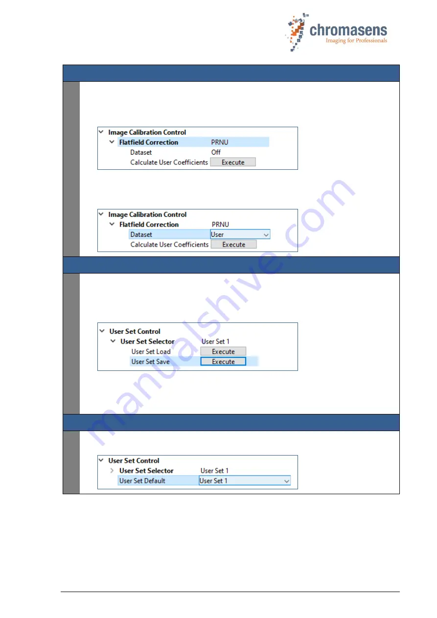
Generate User PRNU correction: 

  At the 

Flatfield Correction

 feature, select 

PRNU

.  

Open the Lens cover and make sure that the white reference target is moving and covers the 
complete  scan  area  for  at  least  300  scan  lines  before  you  execute 

Calculate  User 

Coefficients


This will update/overwrite the user 

PRNU

 correction of the camera. 

  If you want to apply the newly created PRNU correction to subsequent scans, select 

Dataset 

User

 for the PRNU Flatfield Correction. 


Save settings and reference images: 

  If you want the 

User


DSNU

 and 

PRNU


Dataset

 to be activated in 

User Set 1

, save the 

current settings to 

User Set 1

 in the 

User Set Selector

 of the 

User Set Control

 feature 

group by executing the 

User Set Save command

. Please note that the user set only stores 

which dataset to use (

Factory Setting

User

 or 

Off

), not the user DSNU or PRNU 

correction tables itself.  


  Optionally, you can grab and safe an image of the white reference and a dark image for 

reference and backup the user set and DSNU and PRNU correction tables you came up 
with by downloading them from the camera. Refer to the GCT user manual for details on 
downloading those files from the camera. 

Optionally customize your camera boot setting: 

  If you want the camera to boot with the settings saved in 

User Set 1

, select 

User Set 1

 at 

the 

User Set Default 

feature. 


Summary of Contents for allPIXA SWIR CD40199

Page 1: ...allPIXA SWIR GigE Camera Manual CD40199 R01 2022 06 02 PMA_CHR_CD40199_R01_allPIXA_SWIR_GigE_User_Manual docx...

Page 2: ...ra 14 3 4 Purpose applications 14 3 5 Staff requirements 15 3 6 Organizational measurements 15 3 7 Safety instructions for maintenance cleaning 15 3 8 Maintenance and cleaning of the allPIXA SWIR came...

Page 3: ...mera and illumination 35 7 4 Creating flat field correction tables 37 8 Troubleshooting and support 40 8 1 Returning material obtain an RMA number 40 8 2 Temperature warnings and errors 40 8 3 Before...

Page 4: ...y assurance monitoring Customers from all over the world of a wide range of industrial sectors have placed their trust in the experience of Chromasens in the field of industrial image processing 1 1 1...

Page 5: ...ed pattern noise FPN DVAL Data valid Pixel by pixel enabled for Camera Link FFC Flat field correction Can be used to correct the fixed pattern noise of the image sensor the vignetting of the lens and...

Page 6: ...t of data to be transferred or to increase the achievable frame rate RS422 RS 422 TIA EIA 422 Technical standard for Differential Interface Circuits See e g RS 422 Wikipedia SDK Software Development K...

Page 7: ...g plate is located on the rear of the allPIXA SWIR camera It shows the camera resolution and the serial number Additionally ordered and supplied accessories Cables extension rings lenses and other acc...

Page 8: ...illumination 3 has integrated temperature sensors which can be read out with the XLC4 controller By use of the XLC4 controller the illumination unit can be monitored and kept stable 4 Network cable an...

Page 9: ...highlights The allPIXA SWIR camera is especially suitable for inspection systems requiring a very high speed and a consistently high image quality Short wave infrared line scan camera High speed InGaA...

Page 10: ...where the products shall be exported to or shall be imported into 2 4 Technical specification Sensor InGaAs short wave infrared line sensor Spectral sensitivity 950 nm to 1700 nm Resolution 1024 px or...

Page 11: ...e which is available on the allPIXA SWIR download page https chromasens de allpixa swir downloads and to the GenICam Standard Features Naming Convention SFNC which is available free of charge on the G...

Page 12: ...nsor lines of different camera models vary in length depending on maximum resolution and pixel size Figure 2 Camera sensor line location NOTE The logo Chromasens on the side of the camera indicates th...

Page 13: ...n DHCP On Current IP Configuration Persistent IP Off To use DHCP or LLA autoconfiguration you have to disable Persistent IP as this has the highest priority 3 Safety 3 1 Depiction of safety instructio...

Page 14: ...re carrying out any work on the unit Electric voltage hazard The allPIXA SWIR camera runs with electric power Before any work is carried out on the allPIXA SWIR camera be aware to disconnect the mains...

Page 15: ...operation commissioning maintenance and repair must be clearly defined and specified by the owner of the device in which the allPIXA SWIR camera is installed 3 6 Organizational measurements The instru...

Page 16: ...e cleaning the device make sure that the device is disconnected from the power supply All surfaces requiring cleaning can be wiped with a soft lint free cloth which can be moistened with Isopropanol N...

Page 17: ...e with the host application The allPIXA SWIR camera can be used and configured with any GigE Vision 2 0 compliant Software or SDK We recommend using the Chromasens GenICam Control Tool GCT and the Chr...

Page 18: ...2 1024 Pixel size m 25 x 25 12 5 x 12 5 Pixel pitch m 25 12 5 Figure 4 Camera sensor block diagram 4 2 2 Spectral sensitivity The figure below represents the spectral response of the camera sensor spe...

Page 19: ...for power supply A red power LED which indicates whether the allPIXA SWIR camera is connected to the power supply An orange status LED which blinks as soon as the camera firmware has booted successful...

Page 20: ...ailable I O cables see section 9 3 4 You can connect up to three digital input signals and two digital output signals to the digital I O connector of the camera Figure 7 I O connector on camera male f...

Page 21: ...nnection is required additionally between the source for example encoder and the drain camera GND I O ground reference Requirements when using single ended Low Voltage TTL input signals Do not connect...

Page 22: ...ital Output 2 Figure 9 Output schematic Output lines can be configured in the Digital IO Control feature group Please note that this feature Group is only visible in user level Expert or higher not in...

Page 23: ...ce On the backside of the camera you find the following interfaces Two Camera Link MDR connectors for image data transfer and communication between the allPIXA SWIR camera and the image processing com...

Page 24: ...conveyor belt moving with variable speed Adapt camera line rate to transport speed of the object by means of an incremental encoder signal to get undistorted images Refer to section 5 6 and 5 1 3 on...

Page 25: ...this case the rotating direction of the encoder cannot be detected 8 Encoder Divider Float specifies the number of encoder steps needed to generate an encoder output pulse to be used as line trigger...

Page 26: ...fer to section 5 6 and 5 1 3 on how to connect the external line trigger to the digital I O connector of the camera Feature settings in feature group Acquisition Control Trigger Selector Line Start Tr...

Page 27: ...xed Refer to section 5 6 and 5 1 3 on how to connect the light barrier to the digital I O connector of the camera Feature settings in feature group Acquisition Control Trigger Selector Frame Start Tri...

Page 28: ...d flat surface A thermal connection to heat conductive parts has a positive effect on operation of the allPIXA SWIR camera To dissipate the heat more effectively to the surrounding area we also recomm...

Page 29: ...onnected and screwed check the cable configuration The weight of the cables must not be applied to the connectors No other mechanical load should be applied to the connectors Comply with the minimum p...

Page 30: ...o the power supply 5 6 2 Connecting external I O devices to the allPIXA SWIR GigE camera You can connect up to three digital input signals and two digital output signals to the digital I O connector o...

Page 31: ...SE T network connection Use a Cat 5e Cat 6 or better S STP Gigabit Ethernet cable and a suitable Gigabit Ethernet network adapter in the computer Figure 15 Connecting the allPIXA SWIR camera to the co...

Page 32: ...cannot be detected by GCT or if the camera shows up but cannot be opened it may be necessary to adjust the configuration of the network adapter of your computer or the network settings of the camera...

Page 33: ...12 24 VDC 10 typically 6 W see section 5 6 3 Install and configure the network adapter on your PC See GCT manual 4 Adjust the focusing point of your illumination unit and position it correctly Refer t...

Page 34: ...ggers and set the camera to free run mode If you have already changed settings on the camera and do not want to lose them save them in a custom User Set before you load the Default user set To load th...

Page 35: ...lumination visible while adjusting the illumination Special adjustment tools or rulers customized to your scanning system can be very helpful when setting up and aligning camera and illumination To ad...

Page 36: ...p When the Resulting Line Rate drops below your speed requirements defined by camera resolution and transport speed increase illumination intensity LED current or Sensor Gain in the Gain Selector of t...

Page 37: ...erefore make sure to cover front lens and or turn the illumination off before executing the command In a similar way the PRNU calibration wizard will capture and use an image of the moving white refer...

Page 38: ...er Set 1 and download this user setting also to a file on your computer and restore it for later re calibrations To save the current camera settings to User Set 1 select User Set 1 in the User Set Sel...

Page 39: ...RNU Dataset to be activated in User Set 1 save the current settings to User Set 1 in the User Set Selector of the User Set Control feature group by executing the User Set Save command Please note that...

Page 40: ...y Phone 49 0 7531 876 0 Fax 49 0 7531 876 303 E Mail support chromasens de Internet https www chromasens de For return of material you should use the original packaging material to avoid any damages t...

Page 41: ...all relevant information beforehand This ensures fast and efficient problem solving with the Chromasens technical support We recommend using the form in appendix 9 1 as a guideline to collect the mos...

Page 42: ...he problem occur once always regularly rarely please describe Did the application ever run ok yes no If known please describe the reason for the problem or any abnormal behavior Image and Parameter Fi...

Page 43: ..._CHR_CD40199_R01_allPIXA_SWIR_GigE_User_Manual docx 43 9 2 Mechanical specification 9 2 1 Mechanical dimensions of the allPIXA SWIR GigE camera Figure 16 Mechanical dimensions of the allPIXA SWIR came...

Page 44: ...ion CP000430 allPIXA Power Supply 1 5m banana plugs CP000504 allPIXA Power Supply 5m banana plugs T18419 TAG 7 Power Supply cable 5m ferrules The power supply connector is also available separately Ma...

Page 45: ...needed Figure 18 F Mount adapter dimensions Description Description 1 Fastening screw 3 Fastening ring 2 Adapter 4 Release button 9 3 4 I O Cables The I O cable is available in two variants Order Code...

Page 46: ...PMA_CHR_CD40199_R01_allPIXA_SWIR_GigE_User_Manual docx 46 Figure 19 T18445 TAG 7 12 PF HIROSE PLUG STRAIGHT OPEN LEADS CABLE Figure 20 T18446 TAG 7 12 PF HIROSE PLUG RIGHT ANGLE OPEN LEADS Cable...

Page 47: ...PMA_CHR_CD40199_R01_allPIXA_SWIR_GigE_User_Manual docx 47 9 4 EU declaration of conformity for allPIXA SIWR GigE cameras...

Page 48: ...PMA_CHR_CD40199_R01_allPIXA_SWIR_GigE_User_Manual docx 48 9 5 EU declaration of conformity for allPIXA SIWR CameraLink cameras...

Page 49: ...allPIXA_SWIR_GigE_User_Manual docx 49 Chromasens GmbH Max Stromeyer Stra e 116 Phone 49 7531 876 0 https chromasens de 78467 Konstanz Fax 49 7531 876 303 info chromasens de Germany June 2022 Copyright...

Reviews: