Programmable AC/DC Electronic Load 63800 Series Operation & Programming Manual
3-2
3.2
Local/Remote Control
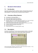
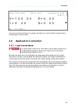
Local (front panel) control is in effect immediately after the power is applied. The front panel
keypad and display allow manual control when Load is used in bench test applications.
Remote control goes into effect as soon as the Load receives a command via GPIB, RS-232C.
When the remote control is in effect, only the computer can control the Load. The front panel
keypad has no effect except the
CONF./LOCAL
key. You can return to local control by
pressing
CONF./LOCAL
key.
Most of the functions that perform remotely can be done locally too at the Load front panel.
Details of local operation are given in
Section
Local Operation
. Fundamentals of remote
programming are described in the latter part of this manual.
3.3
Modes of Operation
In AC load simulation you can select the mode by pressing
CC
,
CR
,
CP
or
RLC/DC RECT
keys under the FUNCTION keypad. In DC load simulation, you can select the mode by
pressing
CC
,
CR
,
CP
,
CV
or
RLC/DC RECT
keys under the FUNCTION keypad. The
parameters in current, resistance, power or rectified load mode can be programmed easily
when the mode is selected.
All data set in any mode will be rescaled to fit the resolution of current/voltage levels, power
value, crest factor (CF) or power factor (PF). In local mode any value can be set to the Load
from the keypad. There is no upper and lower limit that would cause an error. The Load
automatically selects data, which is rescaled from the programmed value, truncates and
checks high, low boundary before fitting it into the memory. When the programmed data is
over the boundary, the Load will be still at original value. In remote mode the programmed
value cannot be over boundary. An error will occur when data is over the maximum or
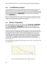
minimum value. The boundary of voltage and current of the load, as well as the power, are
shown in
The operating ambient temperature for the full load is from 0
°
C to 40
°
C, or the OTP will occur
for a period of time.
Figure 3-2 Operating Boundary of Power, Voltage and Current


