13-11-614 Page 30
PROGRAMMING AND SETUP FOR THE AUTO SENTRY W CONTROLLER
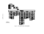
Programming and setup is accomplished with the PROGRAM keys. See Figure 4-2, page 29. In all
steps, the [ENTER] key will cause the controller to accept the displayed value into memory and advance
to the next programming function. The plus [+] and minus [-] keys will increase and decrease displayed
numeric values, or step through menu selections. During numeric adjustments, the right [>] and left [<]
arrow keys move the cursor (flashing digit) to the position desired. Use the [+] and [-] keys to change the
number at the cursor. At any point in the programming and setup routine, the [STOP/RESET] key can be
pressed to exit and return to the ready mode without altering the adjustment. In all steps of the
programming routine, the top line of the display will give a description of the parameter to be
programmed, while the bottom line shows the variable that is capable of being altered by programming.
The following is a step by step guide to programming the AUTO SENTRY W. Remember, between each
step, it is necessary to press the [ENTER] key to store the new value and advance to the next step.
Main Adjustments Menu
1.
The compressor must be stopped prior to making any adjustments. If the unit is running, press
the [STOP/RESET] key to place the control in the “READY” state.
Adjustments can also be performed while in the “SHUTDOWN” state. After the adjustments are
completed, the W controller returns to this state until the cause is repaired and the controller is
manually reset.
2.
Press the [ENTER] key to begin programming. This enters the adjustments menu. The
adjustments are broken into five groups as shown in Figure 4-2, page 29. To select a group,
press [+] or [-] until the desired group is shown on the bottom line of the display. Press [ENTER]
to proceed to the group adjustments detailed below.
Operation Adjustments
1. In the top line, “
DISPLAY UNITS
” is indicated. The bottom line will indicate “ENGLISH” (PSIG,
Fahrenheit) or “METRIC” (Bars, Celsius) units of measurement. Select the desired display units and
press [ENTER] to proceed.
2. The top line displays, “
OPERATING MODE
”. The bottom line will indicate the selected mode. Refer
to the description of modes at the beginning of this chapter, and select the desired mode, using the
[+] or [-] keys. When the desired mode is shown, press the [ENTER] key to save and proceed.
3. In the top line, “
START TIMER
” is displayed. The bottom line will indicate a time between 2 and 10
seconds. This is the time that the controller spends in the unloaded ‘start’ mode. If reduced-voltage
starting is used, it should be set longer than the starter’s timer.
4. In the top line, “
UNLOAD PRESSURE
” is displayed. The bottom line will indicate a pressure value. It
is to be set at the nameplate rating of the compressor for normal operation. Under NO
circumstances, is this adjustment to be set in excess of the compressor nameplate pressure.
5. In the top line, “
LOAD PRESSURE
” is displayed. The bottom line will indicate a pressure value. This
setting determines the point at which machine startup occurs in AUTO and SEQUENCE modes and
when the compressor will load up from the blown down condition. Note that LOAD PRESSURE
cannot be set within 7 PSI of the UNLOAD PRESSURE. It is necessary that all machines to be
sequenced have the same UNLOAD and LOAD PRESSURE setpoints.
Summary of Contents for ROTORCHAMP EWF99C-100
Page 7: ...13 11 614 Page 7 Figure 1 2 PACKAGE ILLUSTRATION AIR COOLED 309EWF797 A Ref Drawing ...
Page 8: ...13 11 614 Page 8 Figure 1 3 PACKAGE ILLUSTRATION WATER COOLED 310EWF797 A Ref Drawing ...
Page 9: ...13 11 614 Page 9 Figure 1 4 AIR COOLED SCHEMATIC 307EWF797 A Ref Drawing ...
Page 10: ...13 11 614 Page 10 Figure 1 5 WATER COOLED SCHEMATIC 308EWF797 A Ref Drawing ...
Page 29: ...13 11 614 Page 29 Figure 4 2 FLOW CHART FOR SETUP PROGRAMMING 300EWC1255 Ref Drawing ...
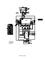
Page 43: ...13 11 614 Page 43 303EWF546 A Ref Drawing Page 2 of 2 ...
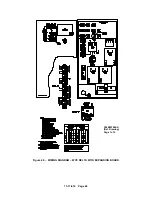
Page 45: ...13 11 614 Page 45 304EWF546 A Ref Drawing Page 2 of 2 ...
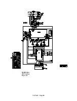
Page 47: ...13 11 614 Page 47 305EWF546 A Ref Drawing Page 2 of 2 ...


