13-11-614 Page 72
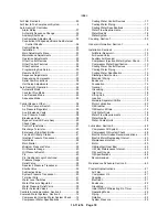
INDEX
Air Filter, Section 6 .........................................................50
Air Flow In The Compressor System ............................6
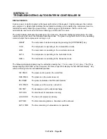
Auto Sentry W Controller
Alarm Relay.................................................................37
Automatic Sequence Change ..................................35
Auxiliary Shutdown....................................................37
Configuration Adjustments .......................................32
Connection Of Expansion Board And External
Control Circuits ......................................................36
Control Display...........................................................25
Installation ...................................................................33
Main Adjustments Menu ...........................................30
Maintenance Adjustments ........................................31
Operation Adjustments .............................................30
Other Control Devices ...............................................38
Other Control Features .............................................33
Other Features ...........................................................36
Programming And Setup ..........................................30
Remote On/Off............................................................37
Sequence Adjustments .............................................31
Sequencing Compressor..........................................33
Serial Communications .............................................38
Unit Setup Adjustments ............................................32
Auto Sentry W Operation..............................................24
Automatic Mode .........................................................25
Constant Run Mode...................................................24
Low Demand Mode ...................................................25
Sequence Mode.........................................................25
Control Devices, Other..................................................38
Air Filter Vacuum Switch ..........................................40
Air Pressure Regulator..............................................39
Aux. Blowdown Vavle................................................38
Aux. Pressure Switch................................................38
Blowdown Valve .........................................................38
Bypass Valve/Oil Pump Assy...................................40
Check Valve ................................................................39
Control Transformer ..................................................41
Discharge Termistor..................................................40
Emergency Stop/Push Button..................................41
Fan And Oil Pump Starter ........................................41
Injection Pressure Transducer.................................40
Inlet Valve ....................................................................39
Main Starter.................................................................41
Minimum Pressure Valve ..........................................39
Oil Pressure Gauge ...................................................40
Oil Pressure Switch ...................................................40
Plc.................................................................................40
Plc (Additional Logic Functions)..............................40
Pressure Gauge .........................................................39
Relief Valve .................................................................38
Reservoir Pressure Transducer ..............................40
Shuttle Valve ...............................................................39
Subtractive Valve .......................................................39
System Pressure Transducer ..................................40
Terminal Strip .............................................................41
Water Level Switches ................................................40
Water Pressure Regulator........................................39
Water Pressure Relief Valve ....................................39
Water Solenoid Valves..............................................40
Controls & Instrumentation, Section 4 ........................24
Coolers & Water Systems, Section 2..........................12
Compression Injection Water System Check........19
Compressor Water Specifications ...........................15
Cooling Water Control Devices ...............................17
Cooling Water Piping ................................................17
Cooling Water Specifications ...................................15
Water Flow Requirements........................................16
Water Quality..............................................................16
Water System ...............................................................6
Coupling, Section 7........................................................52
General Information, Section 1 ......................................6
Installation, Section 2 ....................................................12
Air/Water Reservoir ...................................................19
Air-Cooled Units .........................................................13
Auxiliary Air Receiver ................................................17
Compressor Injection Water System Check .........19
Compressor Water Specification.............................
15
Cooling Water Control Devices ...............................17
Cooling Water Piping ................................................17
Cooling Water Specification .....................................15
Discharge Service Line .............................................18
Electrical Wiring .........................................................19
Enclosure ....................................................................14
Foundation..................................................................14
General........................................................................12
Grounding ...................................................................19
Inlet Line......................................................................18
Lifting Unit ...................................................................12
Location .......................................................................12
Moisture Separator/Orifice .......................................18
Motor Lubrication.......................................................20
Oil Breather.................................................................14
Oil Reservoir Drain ....................................................14
Unit Water Drain ........................................................18
Water Flow Requirements........................................16
Water Quality..............................................................16
Water-Cooled Units ...................................................14
Lubrication, Section 5 ....................................................48
Compressor Oil System............................................48
Compressor Oil System Check ...............................48
Electric Motor Grease Recommendations .............20
Electric Motor Regreasing Interval..........................20
Maintenance Interval.................................................49
Motor ............................................................................20
Oil Breather (Gear Box) ............................................49
Oil Filter Maintenance Interval.................................49
Oil Level Gauge .........................................................49
Oil Specifications .......................................................48
Recommended ...........................................................48
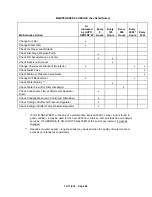
Maintenance Schedule, Section 9...............................60
Prestart-Up Instructions ................................................21
Air Filter........................................................................21
Compressor Oil ..........................................................21
Coupling ......................................................................21
Electrical......................................................................21
Enclosure ....................................................................22
Grounding ...................................................................21
Initial Water Fill/Adjusting Ro Timer ......................22
Operating Mode .........................................................22
Piping ...........................................................................21
Rotation .......................................................................22
System Pressure........................................................22
Summary of Contents for ROTORCHAMP EWF99C-100
Page 7: ...13 11 614 Page 7 Figure 1 2 PACKAGE ILLUSTRATION AIR COOLED 309EWF797 A Ref Drawing ...
Page 8: ...13 11 614 Page 8 Figure 1 3 PACKAGE ILLUSTRATION WATER COOLED 310EWF797 A Ref Drawing ...
Page 9: ...13 11 614 Page 9 Figure 1 4 AIR COOLED SCHEMATIC 307EWF797 A Ref Drawing ...
Page 10: ...13 11 614 Page 10 Figure 1 5 WATER COOLED SCHEMATIC 308EWF797 A Ref Drawing ...
Page 29: ...13 11 614 Page 29 Figure 4 2 FLOW CHART FOR SETUP PROGRAMMING 300EWC1255 Ref Drawing ...
Page 43: ...13 11 614 Page 43 303EWF546 A Ref Drawing Page 2 of 2 ...
Page 45: ...13 11 614 Page 45 304EWF546 A Ref Drawing Page 2 of 2 ...
Page 47: ...13 11 614 Page 47 305EWF546 A Ref Drawing Page 2 of 2 ...

