13-11-614 Page 17
COOLING WATER PIPING
- On packages equipped with water-cooled cores, the water inlet and outlet
are located on the base frame side – See “Package Illustrations”, Figure 1-2 and Figure 1-3, pages 7 & 8,
for details. The pipe network shall be sized to support the maximum required water flow, pressure and
temperature limits listed under the “Water Flow Requirements” table.
COOLING WATER CONTROL DEVICES -
Water cooled packages may be equipped with the following
optional
flow control devices:
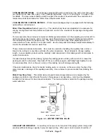
Water Flow Regulation Valve
(Figure 2-3)
–
This (stand alone) device is adjustable to compensate for
varying cooling water inlet temperature and pressure, and is to be mounted in the package cooling water
outlet line.
To
decrease water flow
(increase compressor discharge temperature) turn the adjusting screw from left to
right (increase spring tension), and to
increase water flow
(decrease compressor discharge temperature),
turn the adjusting screw the opposite way. The groove at the lower edge of the adjusting screw is a
visual reference to use with the 0 to 8 index scale. Use the compressor discharge temperature display to
monitor the adjustments made to water flow.
These valves are delicate instruments. Care must be used when handling the capillary tube; a kink or
break in the tubing or connections will make the valve inoperative. Never attempt to change capillary
length – excess capillary tube should be carefully coiled and placed so that damage will not take place in
normal maintenance.
If a leak develops through the packing, tighten the packing gland nut firmly with a wrench to reseat the
packing around the valve stem, then back off the nut until loose again, and finally finger-tighten the nut.
An occasional drop of oil on the valve stem, at the packing nut, will prolong packing life.
If the valve malfunctions, check for bends, binding, paint, or corrosion on the valve stem, fouling of the
valve internals, or damage of the capillary assembly. Use a strainer to prevent solids from blocking the
valve.
Water Flow Stop Valve
– This (stand alone) magnetic solenoid-operated valve is energized by the
package controller to shut off water flow when the package is not operating – refer to wiring diagrams
included in this manual for interconnection details. The device shall be mounted in the package cooling
water outlet line.
Figure 2-3 – WATER CONTROL VALVE
AUXILIARY AIR RECEIVER
- An auxiliary air receiver is not required if the piping system is large and
provides sufficient storage capacity to prevent rapid cycling. When used, an air receiver should be of
Summary of Contents for ROTORCHAMP EWF99C-100
Page 7: ...13 11 614 Page 7 Figure 1 2 PACKAGE ILLUSTRATION AIR COOLED 309EWF797 A Ref Drawing ...
Page 8: ...13 11 614 Page 8 Figure 1 3 PACKAGE ILLUSTRATION WATER COOLED 310EWF797 A Ref Drawing ...
Page 9: ...13 11 614 Page 9 Figure 1 4 AIR COOLED SCHEMATIC 307EWF797 A Ref Drawing ...
Page 10: ...13 11 614 Page 10 Figure 1 5 WATER COOLED SCHEMATIC 308EWF797 A Ref Drawing ...
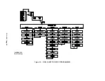
Page 29: ...13 11 614 Page 29 Figure 4 2 FLOW CHART FOR SETUP PROGRAMMING 300EWC1255 Ref Drawing ...
Page 43: ...13 11 614 Page 43 303EWF546 A Ref Drawing Page 2 of 2 ...
Page 45: ...13 11 614 Page 45 304EWF546 A Ref Drawing Page 2 of 2 ...
Page 47: ...13 11 614 Page 47 305EWF546 A Ref Drawing Page 2 of 2 ...


