

13-11-614 Page 52
SECTION 7
COUPLING
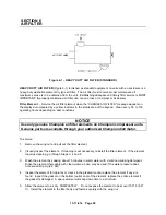
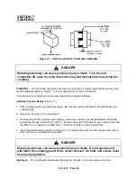
Figure 7-1 – INSTALLATION OF COUPLING CUSHIONS
DANGER
Rotating machinery can cause personal injury or death. Turn the unit
completely off, open the main disconnect, tag and lockout before servicing the
coupling.
COUPLING -
The motor and compressor are direct connected by a resilient type flexible coupling with
several individual cushions, Figure 7-1. The coupling does not require lubrication.
If maintenance on mating parts is required, reassemble coupling as follows:
Individual Cushion Design
(Figure 7-1)
1. Slide coupling halves over shaft extensions. Be sure the collar is installed on the shaft behind one
coupling body.
2. Assemble the motor on the compressor.
3. Working through the coupling guard opening, center the coupling over the gap between the shafts,
maintaining the gap as shown in Figure 7-1, between the ends of the jaws on one coupling body and
the flange on the opposite coupling body. Tighten set screws in each coupling body.
4. Insert individual cushions as shown in Figure 7-1, and slide the collar over the cushions and secure
with cap screws. Reinstall the cover plate.
DANGER
Rotating machinery can cause personal injury or death. Do not operate unit
with either the coupling guard or the collar removed. All bolts and screws must
be properly tightened.
Alignment
- The coupling is permanently aligned by the flanges on the compressor and motor.
Summary of Contents for ROTORCHAMP EWF99C-100
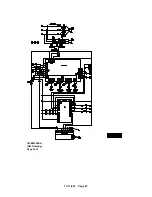
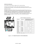
Page 7: ...13 11 614 Page 7 Figure 1 2 PACKAGE ILLUSTRATION AIR COOLED 309EWF797 A Ref Drawing ...
Page 8: ...13 11 614 Page 8 Figure 1 3 PACKAGE ILLUSTRATION WATER COOLED 310EWF797 A Ref Drawing ...
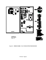
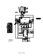
Page 9: ...13 11 614 Page 9 Figure 1 4 AIR COOLED SCHEMATIC 307EWF797 A Ref Drawing ...
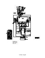
Page 10: ...13 11 614 Page 10 Figure 1 5 WATER COOLED SCHEMATIC 308EWF797 A Ref Drawing ...
Page 29: ...13 11 614 Page 29 Figure 4 2 FLOW CHART FOR SETUP PROGRAMMING 300EWC1255 Ref Drawing ...
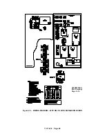
Page 43: ...13 11 614 Page 43 303EWF546 A Ref Drawing Page 2 of 2 ...
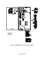
Page 45: ...13 11 614 Page 45 304EWF546 A Ref Drawing Page 2 of 2 ...
Page 47: ...13 11 614 Page 47 305EWF546 A Ref Drawing Page 2 of 2 ...