13-11-614 Page 27
PROTECTIVE SHUTDOWNS
The AUTO SENTRY W will shut down the unit following any fault detected in the following devices. Long-
term problems will have a brief blowdown period before fully shutting down. Following a shutdown, a
message will be displayed, with the top line indicating “SHUTDOWN” and the lower line indicating the
cause. The shutdown light will be steadily lit while the shutdown condition is present, or will flash if the
condition no longer exists. Refer to the troubleshooting section for detailed information about each
shutdown. To resume operation, the cause of the shutdown must be corrected and the controller reset by
pressing the [STOP/RESET] key.
Motor Protective Devices
- Overload heaters are furnished for the starter in the voltage range
specified. There are three (3) overloads in the starter of proper size for the starter and its enclosure.
Note that motor nameplate current must be multiplied by 0.577 for Wye-Delta starters. The display will
indicate that an overload relay has tripped. The overload relay is reset by pressing the button on the
relay itself, then the controller may be reset. Motor current (amps) and voltage must be measured in the
affected motor wiring to locate the cause for high current. Proper starter coil and contact action is also
monitored and errors in operation will cause a shutdown with the cause displayed as a starter or contact
error.
High Temperature
- The compressor is protected from high discharge temperature by a thermistor
probe located in the compressor discharge. The AUTO SENTRY W will shut the compressor down if
temperature exceeds 190
°
F (88
°
C) (or lower per user adjustment) or if rapid temperature rise is
detected. Shutdown will also occur if the temperature falls below freezing. The thermistor probe is also
checked for open or shorted circuits, and the display will indicate a fault, if found.
CAUTION
Machine damage will occur if compressor is repeatedly restarted after high
temperature stops operation. Find and correct the malfunction before resuming
operation.
Water Filter Differential Pressure
- The pressure drop across the water filter is continually monitored
by the AUTO SENTRY W. The unit will be shut down at a differential pressure of approximately 40 psid
(2.8 bars). This becomes active only after the compressor has been running and pressures have had
time to stabilize.
The pressure drop can be monitored at any time by selecting the alternate display “DIF PRES” (water
filter differential pressure) with the [?] HELP key. This should be checked while the compressor is
delivering at full capacity. A service advisory comes on to recommend maintenance prior to this
shutdown.
High Water Level
- If the water management controls are unable to maintain proper water levels, the
compressor will shutdown to prevent damage. Check wiring and piping of the drain and fill solenoid
valves. A shutdown also occurs if wiring errors are detected in the float switch, and the display will
indicate a bad float switch.
High Pressure
- The AUTO SENTRY W will first attempt to unload and blow down the unit if excessive
pressures are detected in the reservoir or the plant system. If unsuccessful, a shutdown will occur. Shut
down will also occur if a defective transducer is detected. The display will indicate the location of the high
sensed pressure or transducer (xducer) error. Check that all adjustments have been properly made, and
all connections are secure.
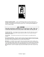
Emergency Stop
- Press the emergency stop button to shut down the unit and the controller. To
restart, pull the button out to its normal position and reset the controller. This should be used for
emergency purposes only - use the keypad [STOP/RESET] for normal controlled stopping.
Summary of Contents for ROTORCHAMP EWF99C-100
Page 7: ...13 11 614 Page 7 Figure 1 2 PACKAGE ILLUSTRATION AIR COOLED 309EWF797 A Ref Drawing ...
Page 8: ...13 11 614 Page 8 Figure 1 3 PACKAGE ILLUSTRATION WATER COOLED 310EWF797 A Ref Drawing ...
Page 9: ...13 11 614 Page 9 Figure 1 4 AIR COOLED SCHEMATIC 307EWF797 A Ref Drawing ...
Page 10: ...13 11 614 Page 10 Figure 1 5 WATER COOLED SCHEMATIC 308EWF797 A Ref Drawing ...
Page 29: ...13 11 614 Page 29 Figure 4 2 FLOW CHART FOR SETUP PROGRAMMING 300EWC1255 Ref Drawing ...
Page 43: ...13 11 614 Page 43 303EWF546 A Ref Drawing Page 2 of 2 ...
Page 45: ...13 11 614 Page 45 304EWF546 A Ref Drawing Page 2 of 2 ...
Page 47: ...13 11 614 Page 47 305EWF546 A Ref Drawing Page 2 of 2 ...


