background image

110524-1

3

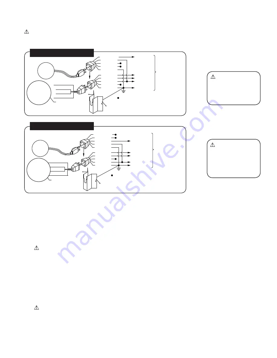
Contractor Model 4000CRLD4

Note:

  This unit comes with the motor, pulley, and thermostat control box installed.  The unit is factory wired and for 120V power.  

The supply power should be adequately protected against overloads and short circuits.

Supply Power to Unit

1.  A disconnect switch (not included) should be installed near the unit.
2.  Run a 2 conductor wire with ground from the power source to the disconnect switch box.
 

CAUTION:  Make sure to use correctly sized wire and follow all local electrical codes.

3.  Remove the screws securing the electrical junction box in the unit to gain access to the power lead wires.
4.  Connect the power leads and ground wire from the unit junction box to the disconnect switch.
5.  Reinstall the junction box to the unit. 

Wall Thermostat Installation

1. 

Find a suitable location for the wall thermostat (away from sources of heat, sunlight, or ventilation, and between 4 and 6 feet 

from the floor).  The thermostat may be mounted to a standard electrical box.

2.  Route an insulated three or four-conductor thermostat cable (or similar) from the Control Box inside the cooler to the 

thermostat electrical box.  This cable is not supplied.  


WARNING:  The thermostat cable should not be routed next to or enter the cabinet through the same inlet as the 

power supply wire.

3. 

Connect the thermostat wires to the terminals on the back of the wall control and to the terminals located on the left side of the 

control box in the unit.  Make sure to follow the color code found next to each terminal.

Blue/Black

White

Brown

Orange

Green

Green

Orange

White

Red

Black

PUMP

HIGH

LOW

COMMON
GROUND

= WIRE NUT

HIGH

LOW

COMMON

GROUND

Black

Green

White

Red

BLOWER MOTOR

PUMP 

MOTOR

TO SWITCH

120 VOLT

COMMON

PUMP 

MOTOR

BLOWER MOTOR

Red

Orange

Green

Black

GROUND

COMMON

LOW

HIGH

= WIRE NUT

GROUND

LOW

HIGH

PUMP

Black

Red

White

Orange

Green

Green

Orange

Brown

White

Blue/Black

TO SWITCH

240 VOLT

CAUTION: 

Recepta-

cles in junction box are 

only for Motor and pump. 

Do not  plug anything 

else into receptacle. 

WARNING: 

Ensure  

cooler cabinet is  proper-

ly grounded to a suitable 

ground connection for 

maximum safety and 

protection of equipment.

6.  Reinstall junction box to cooler cabinet.
7.  Plug motor and pump plugs into receptacles.
8.  Follow switch electrical instructions for connecting the four conductors and power leads to switch.

Warning:  Pump cord must be secured in retaining clip to prevent contact with water.

ELECTRICAL WIRING DIAGRAMS - STANDARD MODEL 4000RLD4

Summary of Contents for 4000 CRLD4

Page 1: ...ill shut motor off when it overheats The motor will restart automatically when it cools down WARNING To reduce the risk of fire or electric shock do not use this fan with any solid state fan speed control device PN 110524 1 REV 11 17 READ CAREFULLY ALL OF THIS MANUAL BEFORE INSTALLING THE UNIT Evaporative cooling is nature s way of cooling When air is moved over a wet surface water is evaporated a...

Page 2: ...ion switch 2 Supply 120V or 240V power to switch depending on motor and pump voltages 3 Remove screws securing junction box to cooler cabinet 4 Bring four conductors plus a ground from switch to cooler junction box CAUTION Make sure to use correctly sized wire and follow all local electrical codes 5 Connect the four conductor wires to the leads of the motor and pump receptacles located in the junc...

Page 3: ...al box This cable is not supplied WARNING The thermostat cable should not be routed next to or enter the cabinet through the same inlet as the power supply wire 3 Connect the thermostat wires to the terminals on the back of the wall control and to the terminals located on the left side of the control box in the unit Make sure to follow the color code found next to each terminal Blue Black White Br...

Page 4: ... Refer to illustration below 1 Remove items 2 3 4 and 5 from float 2 Insert float body through hole in the corner post or float bracket as shown 3 Install washer 2 and nut 3 Tighten to keep float from turning Place nut 5 and ferrule 4 on water supply line Connect to float fitting and tighten until water tight Note After installation is complete and water is turned on the float level will need to b...

Page 5: ...ON DO NOT operate cooler with larger amperage draw than specified on motor plate Motor damage will occur 4 Check belt tension after adjusting pulley A 3 lb force should deflect the belt 3 4 inches Readjust belt if needed by loosening adjustment screw rotate motor until you have the correct belt tension then re tighten screw SCALE BUILDUP PREVENTION As water evaporates minerals that were in the wat...

Page 6: ...w speed If the room temperature rises to 4 degreees above the set temperature the fan will change to high speed and will remain until the room temperature drops to 1 degree above the set point where it will change to low speed The thermostat allows the operator to calibrate the room temperature reading Pressing the up and down arrows simultaneously for 5 seconds will enter the calibration mode A t...

Page 7: ...eration An often misunderstood concept of evaporative cooling is the amount of air that should be exhausted How much should you open your windows The following two methods will help you determine the amount to open your windows WINDOW AREA CFM METHOD For proper air flow allow an opening of at least 2 square feet 288 square inches for each 1000 CFM rating of your unit Example At 3640 CFM model 4000...

Page 8: ...L BEARINGS 1 The blower bearings should be oiled each year with non detergent 20 30 weight oil 2 Locate and open the oil cup on each of the blower bearings and add a few drops of oil CLEAN PUMP 1 Pump should be cleaned at least once a year or more often if debris accumulates 2 Unplug motor and pump from junction box and disconnect pump distribution tube 3 Using a screw driver pry plastic retaining...

Page 9: ...ncrease air flow 2 Belt too loose 2 Adjust belt tension or replace if needed 3 Pads plugged dirty 3 Clean pads 4 Motor underloaded 4 Adjust pulley Water draining onto roof 1 Float arm not adjusted properly 1 Adjust float 2 Overflow assembly leaking 2 Tighten nut and overflow pipe Musty or unpleasant odor 1 Stale or stagnate water in cooler 1 Drain pan and clean pads Motor cycles on and off 1 Low v...

Page 10: ...p Mount 218001 031 218001 031 2 22 Pump 110429 110429 23 Pump Retainer 110714 3 110714 6 24 Purge Pump 110429 25 Pump Mount Extension Bracket 218001 033 218001 033 2 26 Pad Retaining Strap Fastener 110611 24 110611 24 27 Tube Water Delivery 310716 310716 28 Over Flow Assembly 110610 110610 29 Water Distributor Assembly 3D 7 3D 7 30 Holder Water Distributor 110574 8 110574 8 31 Electrical Junction ...

Page 11: ...110524 1 11 PARTS DRAWING ...

Page 12: ...ding failure to perform reasonable maintenance normal wear and tear Alterations include the substitution of name brand components including but not limited to media pads We are not responsible for any damage from the use of water softeners or treatments chemicals or descaling materials We are not responsible for the cost of service calls to diagnose the cause of trouble or labor charge to repair a...

Reviews: