background image

- 11  


O2X 


DUO


Cleaning 

Press ENTER to go to Cleaning program 

Cleaner 

”None”, ”Flush”, or ”Brush”. Do not select “Brush” since this 

does not exist for the O2X  sensor 

Interval min 

0--999 minutes, time between cleaning cycles 

Length sec 

0--999 seconds, duration of flushing cycle 

Freeze sec 

0--999 seconds, extra freeze time of output signal after a 

flushing cycle 

so sensor can go back to the orginal values. 

Relay 

”--”, ”#1”, ”#2”, “Along #1”, or “Along #2”. Select relay to operate 

solenoid for flush cycle, if this sensor is a master with its own 

relay, or relay used by master, if this sensor is a slave. 

These are the same relays used for “Alarm relay” below 

Next time 

The next scheduled cleaning time. Pushing “Enter” on this line 

will reset the time to current time and start a cleaning cycle. 
This could be used to test the “Flush” cycle

Scale / Alarm 

Max 

0--99.9 mg/l, measured value equal to 20 mA output signal. 

Min 

0--99.9 mg/l, measured value equal to 4 mA output signal. 

Hi--Alarm 

0--99.9 mg/l, the value zero inactivates the alarm 

Low--Alarm 

0--99.9 mg/l, the value zero inactivates the alarm 

Alarm Relay 

”--” ”#1”, ”#2”, or ”#1 and #2”. Check to make sure that  the relay 

is not being used for cleaning. 

System 

Type 

Type of sensor, (read only) 

Serial 

Serial number of the sensor, (read only) 

SoftW 

Software version of the sensor, (read only) 

Temp 

Sensor temperature, (read only) 

MaxTemp 

The highest temperature the sensor has been exposed to, (read only) 

Info 

Press “ENTER” to go to “info” (read only) 

MS0 

SA value for zero sample 

MS1 

SA value for air sample 

Cons 1 

Calculated concentration at last air calibration 

Ch1 

Raw value for dissolved oxygen measurement 

Ch2 

Raw value for channel temperature measurement 

Con 

mg/l, This is what is displayed on main screen 

Samp/s 

Number of samples per second 

Service 

Not accessible for users. 

Summary of Contents for O2X Duo

Page 1: ...2018 11 20 C14D5EN19 O2X DUO Dissolved Oxygen Sensor ...

Page 2: ...Mounting the protection plate 7 8 Cleaning the Sensor 8 Cleaning the Flushing Nozzle 9 Mounting plate for solenoid valves 9 9 Sensor display 9 10 Menu for O2X DUO Sensor 10 Settings 10 Calibrate 10 Cleaning 11 Scale Alarm 11 System 11 11 Calibration 12 Zero Calibration 12 Air calibrating a sensor 13 Air pressure conversion 14 12 Scaling 14 13 Technical description 15 Certificate of conformity 15 1...

Page 3: ...e and Silver anode A membrane covers the gold silver electrodes and blocks access of solids to the electrodes Only dissolved gases such as oxygen can pass thru the membrane hence the reduction current responds to the oxygen concentration Active components included in the electrode are treated to maximize their life span Inside the electrode there is also a temperature sensor mounted in a way that ...

Page 4: ...rodes Optical CellsMembranes 10305470 Sensor Holder 11205541 Telescopic Rod 3 sections Fiberglass 4 Meter 13 1 20205652 Stainless steel Handrail Mounting bracket X including rodholder 11205539 Adjustable SS slide rail and sensor holder 66 mm 11205600 Solenoid valve for flushing 230 VAC Inlet hose 16mm 5 8 to sensor 8mm 1 4 11705516A Solenoid valve for flushing 115 VAC Inlet hose 16mm 5 8 to sensor...

Page 5: ...vertical Installation Tips Adjust the rod so that the sensor is at least 30 cm 12 below the liquidsurface or the lowest water level in decant applications SBR s to prevent the sensor from coming out of the liquid In an aeration tank ensure that the sensor is not directly above a diffuser head To obtain the most representative dissolved oxygen level the sensor should be installed on the backside of...

Page 6: ...nd the sensor 7 Changing or installing a new electrode cell The electrode cell can be both assembled and disassembled without special tools Do not clamp the SS sensor housing or the cable when installing or removing the SS flushing head Please note The new optical cell can be mounted on all sensors with serial number higher than 7 25 078 bought later than 1 sept 2014 For older models please contac...

Page 7: ...electrode must be adapted to the holes for the flush pipes Tighten the SS flushing head and mount the protection plate if needed See below the instructions on mounting the protection plate A new air calibration must be performed whenever the electrode cell is changed For the optical cell also a 0 calibration shall be done The date when the electrode cell is changed shall be entered in thecalibrati...

Page 8: ...o be cleaned as a slave along with another sensor then these parameters are set for the sensor being the master Specify the freeze time in seconds after the flush forrecover If the sensor shall be cleaned as master specify the relay to be used according to the wiring inside the control box For example if the solenoid is wired torelay 1 select 1 for flushing If the sensor is to be cleaned as a slav...

Page 9: ...alves for the built in flushing nozzles Cerlic offers a predrilled Aluminum handrail mounting plate The Mounting plate is fixed to the rail using two u bolts Mounting plate P N 10305533 for one or two solenoids outside US version P N 11705516A 11705516 B US Version and a connection box P N 11505748 9 Sensor display By simultaneously pressing and ENTER you change between BB1 BB2 main menu and the s...

Page 10: ...ional information not a precision measurement Temp0 Temperature scaling value that will give max output on second channel Default is 100 C but can be adjusted Calibrate Airpres mB Specify within 10 mBar Go to weather station on internet to obtain for your zip code or location Calibrate No Zero or Air Select what calibration to do Temp info Shows actual temperature in the electrode Test info Shows ...

Page 11: ...o test the Flush cycle Scale Alarm Max 0 99 9 mg l measured value equal to 20 mA output signal Min 0 99 9 mg l measured value equal to 4 mA output signal Hi Alarm 0 99 9 mg l the value zero inactivates the alarm Low Alarm 0 99 9 mg l the value zero inactivates the alarm Alarm Relay 1 2 or 1 and 2 Check to make sure that the relay is not being used for cleaning System Type Type of sensor read only ...

Page 12: ...ug in the cell Zero calibrating a sensor Select the O2X DOU sensor in the Main Menu by using the or buttons Press ENTER for approximately five seconds to enter the SensorMenu Use the arrows to select the Calibration sub menu and pressENTER Select Calibrate Press ENTER Use the arrows to select Zero three choices can be done Air No Zero Press ENTER Wait for the zero calibration to finish usually tak...

Page 13: ... Select the Calibration press ENTER Enter the current air pressure in mBar It is sufficient to specify the pressure within 10 mBar see table below for conversion from inHg to mBar Select Calibrate Press ENTER Use the arrows to select Air three choices can be made Air No Zero Press ENTER Wait for the sensor to be calibrated A successful calibration will take anywhere between 3 to 15 minutes for the...

Page 14: ...or the 4 20mA output signal In addition this menu allows the user to set high and low alarms values that can be used to notify when the level has reached criticalpoints Max sets the 20 mA point output Min sets the 4 mA point output may be a negative valuefor special applications Hi Alarm sets the High Alarm set point the value zero inactivates the alarm Low Alarm sets the Low Alarm set point the v...

Page 15: ...m 33 ft Flushing hose material PE LD Enclosure IP68 NEMA 4X Certificate of conformity The O2X DUO sensors along with their central unit BB1 BB2 Control Box are in conformance with the following EC Directive s when installed in accordance with the installation instructions contained in the product documentation 2014 35 EU Low Voltage Directive LVD 2014 30 EU Electromagnetic Compatibility EMC Direct...

Page 16: ...ssion standard for industrial environments 14 Dimensions Appendix 1 Assembly of handrail mounting kit Mount the Flexible Mounting Bracket on handrail diameter of 1 2 32 50 mm Ø or square 1 1 8 1 5 8 28 42 mm The bent lip on the mounting plate shall be on top and faced toward the liquid or tank Adjust the Mounting Bracket to the correct angle and tighten the SS nuts The bracket shall be fixed to th...

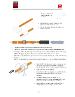
Page 17: ...ervice the instrument wind up a couple of meters of the cable and fasten it on the rail with attached cable tie Hint on pick up let the rod hang freely and lift it straight up before you swing it over the rail Pull the M12 cable and flush hose through the sensor holder and rod Connect the telescoping fiberglass rod to the sensor with the two piece black plastic adapter The adapter halves should be...

Page 18: ...Appendix 2 Assembly of adjustable slide rail ...

Page 19: ... time for five seconds Select System and press ENTER Version Serial Box temp Box heat Leave the BB1 BB2 menu by pressing and ENTER at the same time Use or to select the sensor in the main display Go to the sensor menu it is accessed by pressing ENTER for five seconds Select System and press ENTER Type Serial SoftW Temp Select Info then press ENTER to go to the info menu MS0 MS1 Cons 1 Ch1 Ch2 Con ...

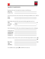
Page 20: ...b menu of the sensor menu the following parameters can be set I time No of decimals Analog Second In the Cleaning sub menu of the sensor menu the following parameters can be set Cleaner Cleaning interval Cleaning length Cleaning freeze Cleaning relay In the Scale Alarm sub menu of the sensor menu the following parameters can be set Max Min High Alarm Low Alarm Alarm Relay Leave the BB2 menu by pre...

Reviews: