Page 37
18. Complex Mode: Option 2 (Ticket vend)
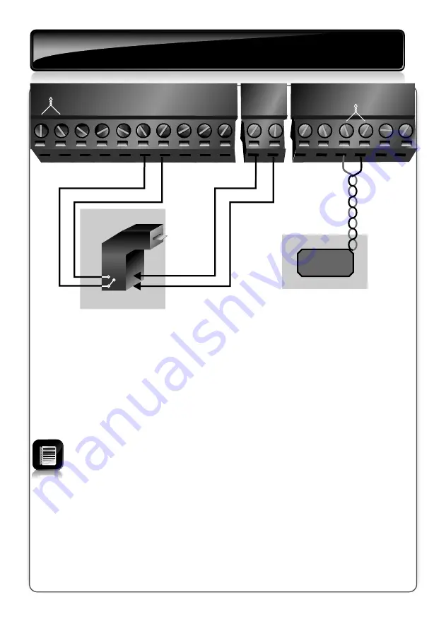
- electrical connections
Safety Beam
FRX
COM
MI
COM
2
3
4
1
5
NMI
Lower
Raise
Status
TVI
TVI
LCK
-12V Out
+12V Out
A
UX Out
Close
7
8
9
10
13
14
11
12
6
15
16
17
18
Safety
loop
Ticket Vend
Option 2: Ticket vending entry points
All connections are made to the termination board and NOT the
controller
(Refer to page 8)
The different inputs to and outputs from the termination board, react
according to the following when
Complex Mode
is selected:
!
Safety Beam:
Although not recommended, this input can be used if a
closing loop detector is not fitted. It is recommended that two safety beams
are used, which are spaced approximately 500 millimetres, horizontally
apart
!
MI:
Typically not used
!
NMI:
Non-memory input responds only when the trigger signal to the input
is removed. It does not react when the signal is given. Connect to the
trigger output from the ticket vending machines
!
Lower:
A dedicated input to only lower the boom pole
!
Raise:
A dedicated input to only raise the boom pole
!
TVI:
Ticket Vend Interlock is a potential-free output that prevents the ticket
vending machine from issuing another ticket until the boom pole is closing
or is closed
!
Close (closing loop):
The FLUX OB onboard loop detector can be used or a
closing loop detector must be fitted. In addition to sensing when the vehicle
has passed the barrier for closing purposes, it will act as a safety loop
preventing the boom pole from being lowered onto a vehicle present on the
loop
FIGURE 39. ELECTRICAL WIRING


