


Installation
38
Rev. 10/17
Brave 30 ES - Brave 60 ES - Brave 90 ES
4.6 Adjusting the carbon
dioxide (CO
2
) supply
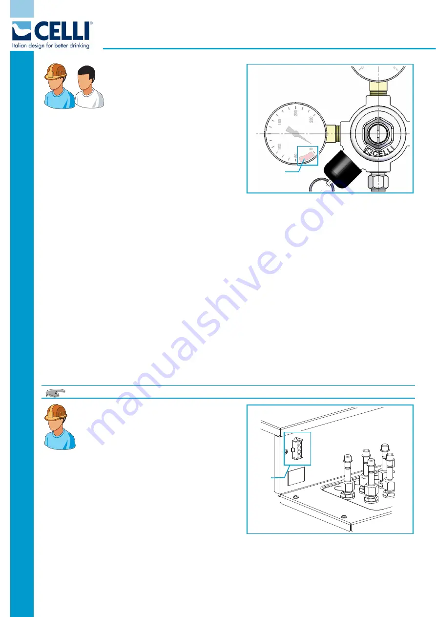
1 -
Slowly open the valve of the CO
2
cylinder until it is fully open. Check
the gas cylinder pressure is always
above the red segment (
A
- low level) of the pressure
reducer pressure gauge; otherwise, the cylinder will have
to be changed.
2 - CO
2
supply to the machine
: turn the adjuster
screw until the needle of the corresponding pressure
gauge reaches 5 bar (73 psi - 0,5 MPa). This value will
depend on the degree of carbonation required.
3 - CO
2
supply to the syrup lines:
•
Syrup in a bag-in-box (BIB):
adjust the supply pressure of the pneumatic pumps to 3 bar (42 psi -
0,3 MPa) - do not exceed 4.8 bar (70 psi - 0,48 MPa).
(Refer to the specifications of the type of pneumatic pump actually used).
•
Syrup in a steel keg:
adjust the pressure to 3 bar (42 psi - 0,3 MPa) for standard syrups, and 1 bar
(14,5 psi - 0,1 MPa) for diet syrups. (Refer to the specifications of the type of syrup actually used).
Connect the plug to a suitable power supply socket, checking that the characteristics of the electricity supply
system correspond to the appliance's technical data.
Make sure the I/0 switch is on
I
, and the pump buttons on the keypad are
ON
.
Check the fan unit and compressor are working. The compressor and fan unit will start with a 4-minute delay
to allow the pressure levels in the circuit to become stable.
After a few minutes, the surface of the condenser starts to heat up; check that this is happening.
If the fan unit and/or compressor are not working, call the after-sales service.
The machine is equipped with an external connector that can be used to obtain a 24V power supply.
Connector (B)
To use for connecting to a dispensing tower
(dispensing valves, any lighting, eventual
buzzer alarm).
The connector supplies 24VAC and 160VA.
For the connection between the machine and
the dispensing tower use cables with a cross-section of
1.5 mm
2
of the H05 VV-F variety.
Do not connect devices different from the dispensing
tower.
BR0181
A
BR0202
B


