


PurePrecision Laser Tape II Scale Installation
IM-Mercury_II_PurePrecision_Scales Rev. 1a
Page 9
©2015 Celera Motion
Mercury II PurePrecision Tape and Glass Scales
Installation Manual
Step
Action
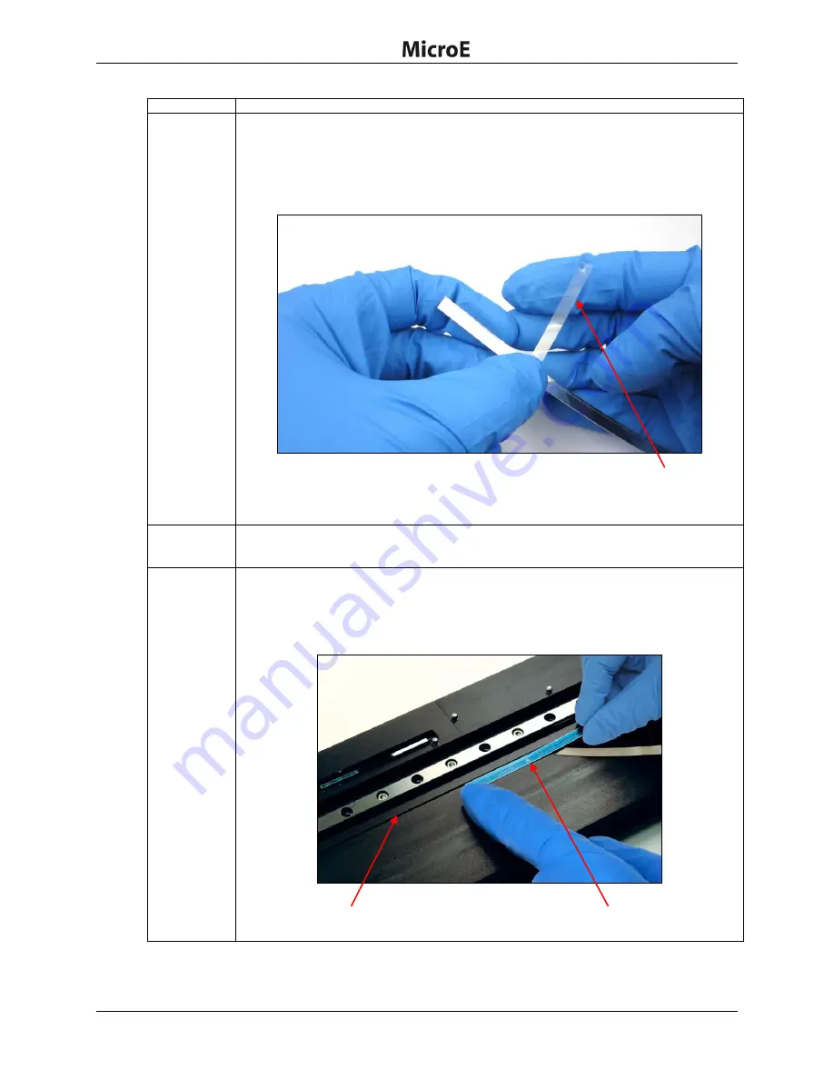
2.
Remove/peel the bottom adhesive backing:
1. Use a sharp tool or fingernails to start peeling the adhesive backing from the left
end of the tape scale.
2. Remove and peel back approximately 25 mm (1 inch) of the bottom adhesive
backing, taking care not to touch the adhesive or allow any particulate
contamination.
Note
:
Be careful not to expose the adhesive backing more than 50 mm (2 inches). Do
not peel the blue protective film off at this time.
3.
Flip the tape over such that exposed adhesive surface of the tape scale (surface from
which the adhesive backing was removed) faces the desired location where the tape
needs to be attached.
4.
Place the tape scale on the mounting surface reference edge:
Place the 25 mm (1 inch) exposed adhesive left end of the tape scale against the mounting
surface
“
D
”
reference edge at the desired starting location and press firmly on the end.
Note
:
Adhesive exposed by removing the adhesive bottom backing can touch the
mounting surface only
once
.
Adhesive backing peeled off about 25 mm (1 inch) from the left end
Tape scale orientation arrow
“D” reference edge as shown in
the encoder interface drawing


