CEBORA S.p.A.
32
3.300.125-C
04/03/2016
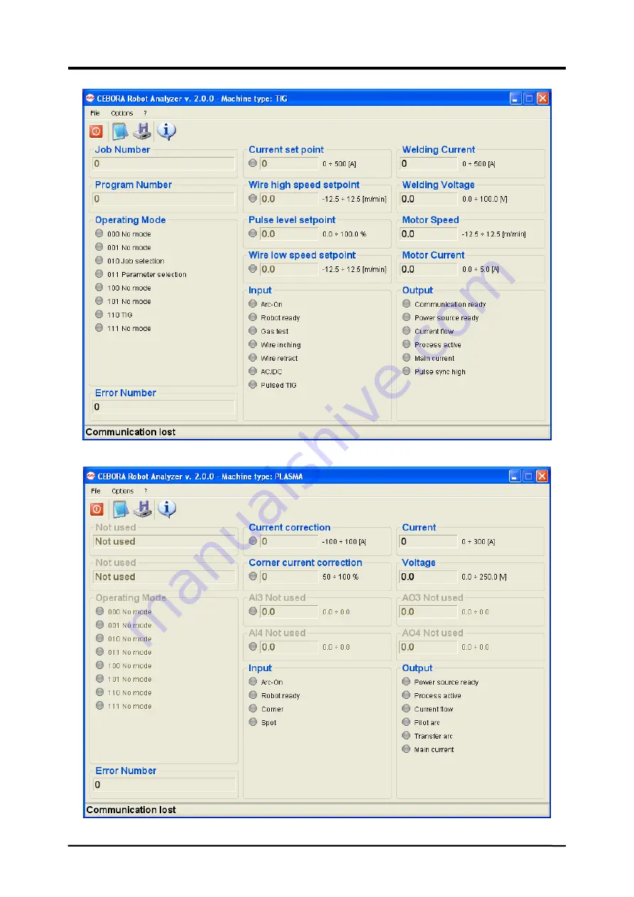
fig. 8b TIG System Main Page.
fig. 8c PLASMA System Main Page.
Page 1: ...NUAL FOR CEBORA ROBOT ANALYZER KIT Art 125 00 pag 11 E MANUAL DE ISTRUCCIONES PARA KIT ANALIZADOR ROBOT CEBORA Art 125 00 pag 20 Finestra di LOG fig 6 LOG Window fig 6 page 29 Ventana del LOG fig 6 Co...
Page 2: ...pacemaker I portatori di apparecchiature elettroniche vitali pacemaker devono consultare il medico prima di avvicinarsi alle operazioni di saldatura ad arco di taglio scriccatura o di saldatura a pun...
Page 3: ...eneratore Robot Pantografo 5 REQUISITI HARDWARE Un Personal Computer IBM compatibile con processore Pentium III o superiore porta USB raccomandata USB 2 0 mouse o dispositivo di puntamento similare Si...
Page 4: ...il nuovo codice Sullo schermo compare la finestra di scelta del processo di lavorazione fig 4 fig 4 Selezionare il Processo di lavorazione su cui installato il Robot Pantografo Click su OK per eseguir...
Page 5: ...Number Se il Program Job richiamato non presente nella tabella il messaggio lampeggiante no PrG visualizzato su Pannello di Controllo NOTA Program Number 0 consente di selezionare un programma da Pann...
Page 6: ...nale di reset il segnale Source Error Reset pu essere collegato al 24 Vdc del Controllo Robot L errore sar resettato appena la causa rimossa NOTA Un errore pu essere correttamente acquisito solo se il...
Page 7: ...a d Arco 11 3 Inductance MIG Indica la Correzione della Induttanza espressa valore assoluto Il campo consentito indicato nella linea La relativa tensione all ingresso analogico dell Interfaccia Robot...
Page 8: ...ografo 12 3 Current Flow Luce Verde indica funzione attiva Il segnale Current Flow inizializzato appena c l arco stabile cio dopo l innesco dell arco 12 4 Process Active Luce Verde indica funzione att...
Page 9: ...stituita Ci rende possible prevenire indesiderate interruzioni del processo di produzione Il circuito watchdog di fine filo impiega un sensore induttivo che campiona costantemente la bobina del filo P...
Page 10: ...ia Robot 13 6 Voltage PLASMA Indica la Tensione d Arco espressa in valore assoluto Il campo consentito indicato nella linea La corrispondente tensione all uscita analogica dell Interfaccia Robot ha il...
Page 11: ...rents may affect the operation of pacemakers Wearers of vital electronic equipment pacemakers shall consult their physician before beginning any arc welding cutting gouging or spot welding operations...
Page 12: ...ce Robot Pantograph System 5 HARDWARE REQUIREMENTS A Personal Computer IBM compatible with Pentium III or higher class processor USB port USB 2 0 recommended mouse or similar pointing device Operating...
Page 13: ...licking the change license button fig 4 and typing the new code On the screen appears of working process chosing window fig 4 fig 4 Select the working Process according with the Robot Pantograph insta...
Page 14: ...gram Number If the Program Job recalled is not present in the table no PrG blinking message is displayed on the Control Panel NOTE Program Number 0 allows to select a program on the Control Panel usin...
Page 15: ...4 Vdc on the Robot Control The error is then reset as soon as the cause of the error has been remedied NOTE An error can only be acknowledged properly if the Source Error Reset signal remains initiali...
Page 16: ...s neutral inductance basic setting 9 9 means soft arc with little or no spatter 11 4 Burn back Time Correction MIG Indicates the Burn back Time Correction expressed in msec The allowed range is shown...
Page 17: ...nal fig 5 The Process Active signal helps to ensure optimum gas shielding by ensuring that the Robot Pantograph dwells sufficiently long at the beginning and end of the weld seam or cut 12 5 Main Curr...
Page 18: ...d high level current welding Red light indicates TIG pulsed low level current welding During welding green and red indicators light alternatively at Pulsed frequency With Pulsed frequency higher than...
Page 19: ...ESCRIPTION Log Window fig 6 contents information referred to modified parameters variations with the following indication for each parameter Parameter new value Parameter type Transmission time dd mm...
Page 20: ...itales pacemaker deben consultar el m dico antes de acercarse a las operaciones de soldadura de arco de corte desagrietamiento o de soldadura por puntos La exposici n a los campos electromagn ticos de...
Page 21: ...grafo 5 REQUISITOS HARDWARE Un Personal Computer IBM compatible con procesador Pentium III o superior puerta USB se recomienda USB 2 0 rat n o dispositivo puntero similar Sistema Operativo Windows 200...
Page 22: ...gitando el nuevo c digo En la pantalla aparece la ventana de elecci n del proceso de trabajo fig 4 fig 4 Seleccionar el Proceso de trabajo correspondiente al Robot Pantografo instalado Clic en OK para...
Page 23: ...dio de un Program Number Si el Program Job llamado no estuviera en la tabla el mensaje centelleante no PrG viene visualizado en el Tablero de Control NOTA Program Number 0 permite seleccionar un progr...
Page 24: ...l Robot no tiene la se al de reset la se al Source Error Reset puede ser conectado al 24 Vdc del Control Robot L error ser reseteado apenas se quita la causa del error NOTA Un error puede ser adquirid...
Page 25: ...l Arco 11 3 Inductance MIG Indica la Correcci n de la Inductancia expresa en valor absoluto El campo concurrido se indica en la l nea La relativa tensi n a la entrada anal gica del Interfaz Robot tien...
Page 26: ...es del Robot Pantografo 12 3 Current Flow Luz Verde indica funci n activa La se al Current Flow se inicializa al presentarse el arco estable despu s del inicio del encendido del arco 12 4 Process Acti...
Page 27: ...pronto deber ser sustituida Esto permite prevenir interrupciones no deseadas del proceso de producci n El circuito watchdog de final del hilo emplea un sensor inductivo que muestrea constantemente la...
Page 28: ...r de la Tension de Arco expreso en valor absoluto El campo concurrido se indica en la l nea La relativa tensi n a la salida anal gica del Interfaz Robot tiene la siguiente relaci n 0 0 250 0 V de Tens...
Page 29: ...CEBORA S p A 29 3 300 125 C 04 03 2016 I Finestra di LOG par 14 GB LOG window par 14 E Ventana del LOG par 14 fig 6...
Page 30: ...ce Robot Interface CANopen cable in Robot Interface 5 Robot Control cabinet 6 Welding wire spool holder 7 Torch 8 Wire Feeder unit 10 Welding wire sheath 21 Power Source 22 Cooling Unit 24 Power Sourc...
Page 31: ...CEBORA S p A 31 3 300 125 C 04 03 2016 fig 7b PLASMA system fig 8a MIG System Main Page...
Page 32: ...CEBORA S p A 32 3 300 125 C 04 03 2016 fig 8b TIG System Main Page fig 8c PLASMA System Main Page...