Operating instructions
22
6
Operating
instructions
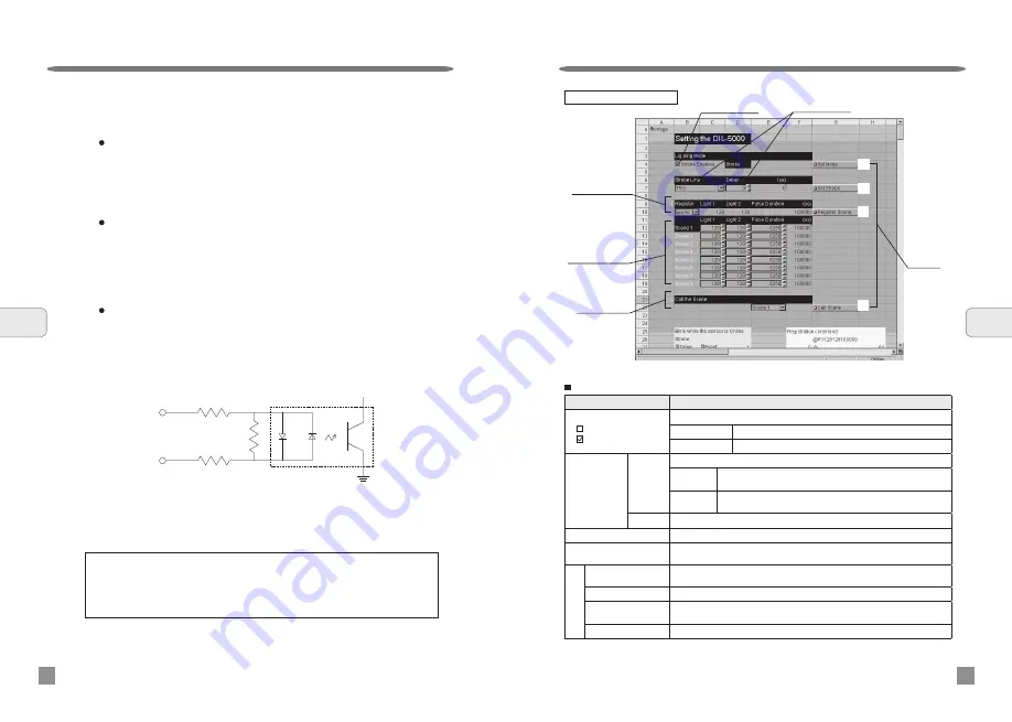
Mode selection
Strobe setting
Display of
scene selected
Display of list of
scenes
Function
buttons
Default values: Light control; 128, Light pulse width; 100000, Emission timing; 0, Delay time; 0000
(1)
List of setting job functions
Function
Description
Mode selection
: Always
: Strobe Enabled
Used to select light control method.
Always
Used for stationary light.
Strobe Enabled
Used for strobe light (with no overdrive).
Strobe setting
Note: Enabled
only when strobe
light mode is
selected.
Pulse
timing
Used to select a trigger signal.
TRG
Use a trigger output from external control equipment such as a PLC.
(Trigger port No.0)
HSOUT1
Use high-speed output from the In-Sight5000 as a trigger.
(Trigger port No.1)
Delay time
Used to set to a total of 64 steps in 16-μs units in the range of 0 to 1,008μs.
Display of scene selected
Select the current scene and display it.
Display of list of scenes
Indicates datas for every sequence.
Make settings of light control data and pulse duration by scene.
Fu
nc
tio
n b
utt
on
s
(1)Set Mode button
Used to transmit an instruction to shift the system to mode selected to the DIL
interface unit.
(2)Set Strobe button
Used to transmit the set values of trigger port and delay time to the DIL interface unit.
(3)Register Scene button Used to transmit every scene data to the DIL interface unit and save it in the internal
memory.
(4)Call the Scene button Used to call scene data saved in the internal memory of the DIL interface unit.
For detail of strobe setting, please refer to information on page 14.
For detail of settings of light control and light pulse width, please refer to information on page 15.
Call the Scene
2.
2k
4.7k
TRG -
TRG +
4.7k
Operating instructions
21
For the use of the In-Sight 5000 series from Cognex, thoroughly read its
User manual.
For the use of the extension I/O module 1450 or 1460 from Cognex,
thoroughly read their User manual.
(2)
(3)
(4)
In order to use external control equipment output, such as a pull-down
type PLC, as a trigger:
Connect “TRG+” to +24V and “TRG-” to output. If the output turns
ON, “TRG-” will be pulled down to 0V, and the input photocoupler will
turn ON.
*It uses external control equipment, such as an extension I/O module or a PLC,
directly as a trigger.
2) When the Trigger Port “No. 0” is used
In order to use external control equipment output, such as a pull-up type
PLC, as the trigger:
Connect “TRG+” to output and “TRG-” to 0V. If the output turns ON,
“TRG+” will be pulled up to 24V, and the input photocoupler will turn
ON.
If the extension I/O module 1450 or 1460 from Cognex is used, connect
the “PIN 2” of the terminal block of the extension I/O module to “TRG+” and
“PIN 3” to “TRG-”.
Trigger input circuit diagram
Note: Please refer to page 15 for response time after receiving trigger.
Setting Job window
6
Operating
instructions


