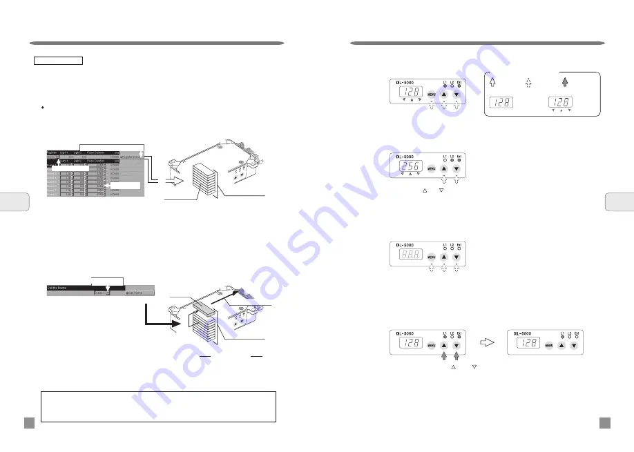
Example: Call “Scene 3”.
Select “Scene 3” on the select scene display, and then click on the Scene call button.
Data on “Scene 3” saved in the DIL interface unit will be rewritten to output data.
Save and call of scene data
Example: Save scene data
To make setting of scenes 1 to 8, enter set values of Light1, Light2, and pulse duration,
respectively. Subsequently, click on the Regoster Scene button to save scene data
with the DIL interface unit. The DIL interface unit constantly overwrites and saves the
scene data received.
Note: For detail of light control data and pulse duration, please refer to information on page 15.
Operating instructions
Panel display while in external control mode:
Pressing the “ ” or “ ” button will turn OFF the L1 lamp and ON the L2 indication lamp,
and display the light control data of L2 on the digital window.
Pressing and holding the “ ” and “ ” buttons at one time for 3 seconds or more will
shift external control to manual control.
(When the mode is shifted, the light control data of L1 and L2 for external control will be
both carried over.)
External control/ Manual control selection
If no key operation is performed for 10 seconds, the display light will go out once. If any
of the three buttons is pressed, the display light will be on.
Other display
6
Operating
instructions
24
Operating instructions
23
6
Operating
instructions
The set values of light control data (Light1, Light2) and pulse duration can be
registered by scene. Furthermore, a maximum of 8 scene data can be registered.
The scene data registered are saved in the internal memory of the DIL interface
unit.
When an equipment connected to the DIL interface unit is changed;
Data before change is saved in the DIL interface unit. After the connecting
equipment is changed, please save new setting before usage.
Job window
Call “Scene 3”.
シーン
3
Scene 8
Scene 7
Scene 6
Scene 5
Scene 4
Scene 3
Scene 2
Scene 1
Scene 3
Internal memory
Output “Scene 3”.
Scene 3
DIL interface unit
(Internal memory)
Image Figure
Just press the
button.
Just press either
button.
Press and hold
the button.
Meaning of indication by arrow
Continuous
light
Blinking
Light control data can be checked
on the digital window while in external control mode.
Pressing any of the buttons on the operation panel will turn ON the L1 and Ext indication
lamps, and it displays the light control data of L1 on the digital window.
Scene 8
Scene 7
Scene 6
Scene 5
Scene 4
Scene 3
Scene 2
Scene 1
Internal memory
DIL interface unit
(Internal memory)
Job window
R
eg
ist
ra
tio
n
Scene data
Selecting a scene
Registering a selected scene
Scenes 1 to 8
Select Scene 3
Scene data


