background image

16–Using Cavium Teaming Services
Executive Summary

205

83840-546-00  N

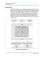
Smart Load Balancing enables both transmit and receive load balancing based on 
the Layer 3 and Layer 4 IP address and TCP/UDP port number. In other words, 
the load balancing is not done at a byte or frame level but on a TCP/UDP session 
basis. This methodology is required to maintain in-order delivery of frames that 
belong to the same socket conversation. Load balancing is supported on 2 to 8 
ports. These ports can include any combination of add-in adapters and LAN on 
motherboard (LOM) devices. Transmit load balancing is achieved by creating a 
hashing table using the source and destination IP addresses and TCP/UDP port 
numbers. The same combination of source and destination IP addresses and 
TCP/UDP port numbers will generally yield the same hash index and therefore 
point to the same port in the team. When a port is selected to carry all the frames 
of a specific socket, the unique MAC address of the physical adapter is included in 
the frame, and not the team MAC address. This is required to comply with the 
IEEE 802.3 standard. If two adapters transmit using the same MAC address, then 
a duplicate MAC address situation would occur that the switch could not handle. 

Receive load balancing is achieved through an intermediate driver by sending 
gratuitous ARPs on a client-by-client basis using the unicast address of each 
client as the destination address of the ARP Request (also known as a directed 
ARP). This is considered client load balancing and not traffic load balancing. 
When the intermediate driver detects a significant load imbalance between the 
physical adapters in an SLB team, it will generate G-ARPs in an effort to 
redistribute incoming frames. The intermediate driver (QLASP) does not answer 
ARP Requests; only the software protocol stack provides the required ARP Reply. 
It is important to understand that receive load balancing is a function of the 
quantity of clients that are connecting to the system through the team interface. 

SLB receive load balancing attempts to load balance incoming traffic for client 
machines across physical ports in the team. It uses a modified gratuitous ARP to 
advertise a different MAC address for the team IP Address in the sender physical 
and protocol address. This G-ARP is unicast with the MAC and IP Address of a 
client machine in the target physical and protocol address respectively. This 
causes the target client to update its ARP cache with a new MAC address map to 
the team IP address. G-ARPs are not broadcast because this would cause all 
clients to send their traffic to the same port. As a result, the benefits achieved 
through client load balancing would be eliminated, and could cause out-of-order 
frame delivery. This receive load balancing scheme works as long as all clients 
and the teamed system are on the same subnet or broadcast domain. 

NOTE

IPv6 addressed traffic will not be load balanced by SLB because ARP is not 
a feature of IPv6. 

Summary of Contents for FastLinQ 3400 Series

Page 1: ...83840 546 00 N User s Guide Converged Network Adapters and Intelligent Ethernet Adapters FastLinQ 3400 and 8400 Series ...

Page 2: ...m All In the NOTE added instructions for uninstalling QSC GUI in Linux systems Preface on page xxi Updated the instructions for submitting a case with technical support Technical Support on page xxvi Updated the instructions for downloading updates and documentation Downloading Updates and Documentation on page xxvi Updated the instructions for accessing the knowl edgebase Knowledge Database on pa...

Page 3: ... error_mask1 and error_mask2 driver parameters bnx2i Driver Parameters on page 42 Added cnic driver parameters cnic Driver Parameters on page 45 Updated Figure 7 2 Download Install and Update Drivers on page 49 Added VMware driver parameters for cnic qfle3 qfle3i qfle3f cnic Driver Parameters on page 56 qfle3 Driver Parameters on page 56 qfle3i Driver Parame ters on page 60 qfle3f Driver Parameter...

Page 4: ...to Teams on page 190 In the third paragraph fourth sentence clarified that QLASP VLANs are supported only with homogeneous teaming and not in a multivendor teaming environment Added a new last paragraph indicating that QLASP is for OSs that do not support in OS NIC teaming IEEE 802 1Q VLANs on page 226 Revised an expanded this section to further describe VLAN filtering and QinQ Added instruc tions...

Page 5: ...LB Team Connected to a Single Hub on page 237 Added QLASP to title and text where appropriate QLASP Teaming with Microsoft NLB on page 237 Corrected the answer to Where can I get the lat est supported drivers to the Marvell Web page Frequently Asked Questions on page 248 Added a new problem iSCSI offload issue with RHEL 7 6 and corresponding solution Linux Issues on page 278 ...

Page 6: ... Notices xxvii Warranty xxvii Laser Safety FDA Notice xxviii Agency Certification xxviii EMI and EMC Requirements xxviii KCC Class A xxix VCCI Class A xxx Product Safety Compliance xxx 1 Product Overview Functional Description 1 Features 2 iSCSI 5 FCoE 5 Power Management 5 Adaptive Interrupt Frequency 6 ASIC with Embedded RISC Processor 6 Adapter Management 6 QLogic Control Suite CLI 6 QLogic QCon...

Page 7: ...ulti Boot Agent Driver Software Overview 14 Setting Up MBA in a Client Environment 15 Enabling the MBA Driver 15 Configuring the MBA Driver 15 Controlling EEE 17 Setting Up the BIOS 17 Setting Up MBA in a Server Environment 17 Red Hat Linux PXE Server 17 MS DOS UNDI or Intel APITEST 18 4 Windows Driver Software Windows Drivers 20 Installing the Driver Software 21 Using the Installer 22 Using Silen...

Page 8: ...Run Necessary iSCSI Software Components 34 Unloading or Removing the Linux Driver 34 Unloading or Removing the Driver from an RPM Installation 34 Uninstalling QCC GUI 35 Patching PCI Files Optional 35 Network Installations 36 Setting Values for Optional Properties 36 bnx2x Driver Parameters 36 int_mode 36 disable_tpa 37 dropless_fc 37 disable_iscsi_ooo 37 multi_mode 38 num_queues 38 full_promiscou...

Page 9: ... tcp_buf_size 44 debug_logging 44 bnx2i_ssan_feature 44 ooo_enable 45 bnx2fc Driver Parameters 45 bnx2fc_debug_logging 45 cnic Driver Parameters 45 cnic_debug 45 cnic_dump_kwqe_enable 46 Driver Defaults 46 bnx2x Driver Defaults 46 Teaming with Channel Bonding 46 Statistics 47 7 VMware Driver Software VMware Drivers 48 Packaging 49 Download Install and Update Drivers 49 Driver Parameters 53 bnx2x D...

Page 10: ...nable_lro 57 hw_vlan 57 intr_mode 58 mtu 58 offload_flags 58 multi_rx_filters 58 rxqueue_nr 58 rxring_bd_nr 58 txqueue_nr 59 txring_bd_nr 59 RSS 59 DRSS 59 rss_engine_nr 59 enable_vxlan_filters 59 dropless_fc 60 max_vfs 60 qfle3i Driver Parameters 60 qfle3i_chip_cmd_max 60 qfle3i_esx_mtu_max 60 qfle3i_max_sectors 60 qfle3i_max_task_pgs 61 qfle3i_nopout_when_cmds_active 61 cmd_cmpl_per_work 61 en_h...

Page 11: ..._Entry 64 Driver Defaults 65 bnx2x Driver Defaults 65 qfle3 Driver Defaults 65 Unloading and Removing Driver 66 Driver Messages 66 Driver Sign On 66 NIC Detected 66 MSI X Enabled Successfully 67 Link Up and Speed Indication 67 Link Down Indication 67 Memory Limitation 67 Multiqueue and NetQueue 67 FCoE Support 68 Enabling FCoE 68 Verifying Installation 70 Limitations 70 Supported Distributions 70 ...

Page 12: ...ttings in Windows Environments 109 Virtual LANs 109 Creating an iSCSI Boot Image with the dd Method 109 Troubleshooting iSCSI Boot 110 iSCSI Crash Dump 112 iSCSI Offload in Windows Server 112 Installing Cavium Drivers 113 Enabling and Disabling iSCSI Offload 113 Installing the Microsoft iSCSI Initiator 114 Configuring Microsoft Initiator to Use Cavium s iSCSI Offload 115 iSCSI Offload FAQs 122 Eve...

Page 13: ...g Cavium Multi Boot Agent for FCoE Boot 139 UEFI Boot LUN Scanning 143 FCoE Boot Installation 143 Windows Server 2008 SP2 FCoE Boot Installation 144 Windows Server 2012 2012 R2 and 2016 FCoE Boot Installation 146 Linux FCoE Boot Installation 147 Adding Additional Linux Boot Paths 163 VMware ESXi FCoE Boot Installation 167 Booting from SAN After Installation 172 Driver Upgrade on Linux Boot from SA...

Page 14: ... Upgrading Windows Operating Systems 186 13 Using Virtual LANs in Windows VLAN Overview 187 Adding VLANs to Teams 190 14 Enabling SR IOV Overview 191 Enabling SR IOV 191 SR IOV and Storage 193 SR IOV and Jumbo Packets 193 15 Configuring Data Center Bridging Overview 194 Enhanced Transmission Selection 194 Priority based Flow Control 195 Data Center Bridging Exchange 195 Configuring DCB 196 DCB Con...

Page 15: ...ch dependent Generic Static Trunking 218 Switch dependent Dynamic Trunking 220 LiveLink 221 Attributes of the Features Associated with Each Type of Team 221 Speeds Supported for Each Type of Team 223 Teaming and Other Advanced Networking Properties 224 Checksum Offload 225 IEEE 802 1p QoS Tagging 225 Large Send Offload 225 Jumbo Frames 226 IEEE 802 1Q VLANs 226 IEEE 802 1ad Provider Bridges QinQ 2...

Page 16: ...43 Fault Tolerance 245 Troubleshooting Teaming Problems 246 Teaming Configuration Tips 246 Troubleshooting Guidelines 247 Frequently Asked Questions 248 Event Log Messages 251 Windows System Event Log Messages 251 Base Driver Physical Adapter or Miniport Messages 252 Intermediate Driver Virtual Adapter or Team Messages 255 Virtual Bus Driver Messages 258 17 Configuring Teaming in Windows Server QL...

Page 17: ...stics 265 Diagnostic Test Descriptions 268 A Troubleshooting Hardware Diagnostics 272 QCC GUI Diagnostic Tests Failures 272 QCC Network Test Failures 273 Checking Port LEDs 273 Troubleshooting Checklist 273 Checking if Current Drivers are Loaded 274 Possible Problems and Solutions 276 Multi Boot Agent Issues 276 QLASP Issues 276 Linux Issues 278 NPAR Issues 280 Miscellaneous Issues 280 B Adapter L...

Page 18: ...s Multiboot Agent Configuration 108 9 11 Configuring iSCSI Boot VLAN 108 9 12 Saving the iSCSI Boot VLAN Configuration 108 9 13 Enabling or Disabling iSCSI Offload on Windows 114 9 14 iSCSI Initiator Properties 115 9 15 iSCSI Initiator Node Name Change 116 9 16 iSCSI Initiator Add a Target Portal 116 9 17 Target Portal IP Address 117 9 18 Selecting the Local Adapter 118 9 19 Selecting the Initiato...

Page 19: ...oE Disks 157 10 28 Installation Summary Page 158 10 29 Installation Destination Page 159 10 30 ESXi Installation Boot Menu 167 10 31 ESXi Installation Welcome Window 167 10 32 ESXi Installation Select Disk 168 10 33 ESXi Installation Select Install Method 168 10 34 ESXi Installation Select Keyboard Layout 169 10 35 ESXi Installation Enter Password 169 10 36 ESXi Installation Confirm Installation 1...

Page 20: ...ion 17 Suboption Definition 95 9 5 Offload iSCSI OIS Driver Event Log Messages 122 12 1 Configurable Network Adapter Hyper V Features 181 12 2 Configurable Teamed Network Adapter Hyper V Features 183 13 1 Example VLAN Network Topology 189 16 1 Teaming Terminology 200 16 2 Available Teaming Types 204 16 3 Comparison of Team Types 210 16 4 Team Type Attributes 221 16 5 Link Speeds in Teaming 223 16 ...

Page 21: ... all Cavium adapters The QLogic Control Suite QCS GUI is no longer supported for the 8400 3400 Series Adapters and adapters based on 57xx 57xxx controllers and has been replaced by the QCC GUI management tool QCC GUI provides single pane of glass GUI management for all Cavium adapters In Windows environments when you run QCS CLI and the Management Agents Installer it will uninstall QCS GUI if inst...

Page 22: ... a pre installation checklist Chapter 3 Setting Up Multi Boot Agent Driver Software describes the software module that allows your network computer to boot with the images provided by remote servers across the network Chapter 4 Windows Driver Software describes Windows driver installation and removal management application installation adapter properties management and power management options Cha...

Page 23: ...vices to provide fault tolerance and load balancing Chapter 17 Configuring Teaming in Windows Server describes the teaming configuration for Windows Server operating systems Chapter 18 Running User Diagnostics in DOS describes the MS DOS based application that runs diagnostic tests updates device firmware and manages adapter properties Appendix A Troubleshooting describes a variety of troubleshoot...

Page 24: ...fication Options select the Warning Alarms check box Text in Courier font indicates a file name directory path or command line text For example To return to the root directory from anywhere in the file structure Type cd root and press ENTER Issue the following command sh install bin Key names and key strokes are indicated with UPPERCASE Press CTRL P Press the UP ARROW key Text in italics indicates...

Page 25: ... indicates mutually exclusive options select one option only For example on off 1 2 3 4 ellipsis indicates that the preceding item may be repeated For example x means one or more instances of x x means zero or more instances of x parentheses and braces are used to avoid logical ambiguity For example a b c is ambiguous a b c means a or b followed by c a b c means either a or b c License Agreements ...

Page 26: ... directed to a page to create a support account If you have an account enter your User Name and Password and then click Sign In 5 From the links at the top of the page click Submit a Case Downloading Updates and Documentation The Marvell Web site provides periodic updates to product firmware software and documentation 1 Go to www marvell com 2 Point to Support Under Driver Downloads click Marvell ...

Page 27: ...ter QLogic Fibre Channel Adapters and Controllers FastLinQ LiquidIO Ethernet Adapters and Controllers 4 Under Related Links click Knowledgebase Legal Notices Legal notices covered in this section include warranty laser safety FDA notice agency certification and product safety compliance Warranty Warranty details for your product are available on the Marvell Web site To obtain warranty information ...

Page 28: ...ding interference that may cause undesired operation Industry Canada ICES 003 2012 Class A This Class A digital apparatus complies with Canadian ICES 003 Cet appareil numériqué de la classe A est conformé à la norme NMB 003 du Canada CE Mark 2004 108 EC EMC Directive Compliance EN55032 2012 CISPR 32 2015 Class A EN55024 2010 EN61000 3 2 2006 A1 A2 2009 Harmonic Current Emission EN61000 3 3 2008 Vo...

Page 29: ...t Ethernet Adapters Certification holder QLogic Corporation Manufactured date Refer to date code listed on product Manufacturer Country of origin QLogic Corporation USA A class equipment Business purpose info telecommunications equipment As this equipment has undergone EMC registration for busi ness purpose the seller and or the buyer is asked to beware of this point and in case a wrongful sale or...

Page 30: ...radio interference may occur in which case the user may be required to take corrective actions Product Safety Compliance UL cUL product safety UL60950 1 2nd Edition 2007 UL CSA C22 2 60950 1 07 2nd Edition 2007 Use only with listed ITE or equivalent Complies with 21 CFR 1040 10 and 1040 11 2006 95 EC low voltage directive TUV EN60950 1 2006 A11 A1 A12 2nd edition TUV IEC60950 1 2006 2nd Edition Am...

Page 31: ...rk The C NIC offers acceleration for popular protocols used in the data center such as Internet Small Computer Systems Interface iSCSI offload for accelerating network storage access featuring centralized boot iSCSI boot Fibre Channel over Ethernet FCoE offload and acceleration for Fibre Channel block storage Enterprise networks that use multiple protocols and multiple network fabrics benefit from...

Page 32: ...13 Using Virtual LANs in Windows For instructions on configuring teaming and creating VLANs on Windows operating systems see Configuring Teaming on page 210 Features Cavium 8400 3400 Series Adapters feature the following Some features may not be available on all adapters iSCSI offload FCoE offload NIC partitioning NPAR Data center bridging DCB Enhanced transmission selection ETS IEEE 802 1Qaz Prio...

Page 33: ...inQ ESXCLI VMware Plug in part number BC0151101 00 QCC PowerKit for Windows and Linux For information see the User s Guide PowerShell part number BC0054518 00 QLogic Comprehensive Configuration Management Pre boot Utility For more information see the User s Guide Comprehensive Configuration Management QLogic 3400 and 8400 Series Adapters part number BC0054512 00 VMware For information see the User...

Page 34: ...erver 2008 R2 2012 2012 R2 Logical link control IEEE Std 802 2 High speed on chip reduced instruction set computer RISC processor Integrated 96KB frame buffer memory Quality of service QoS Serial gigabit media independent interface SGMII Gigabit media independent interface GMII Media independent interface MII 256 unique MAC unicast addresses Support for multicast addresses through the 128 bits has...

Page 35: ...future OS convergence and integration Therefore the adapters iSCSI offload architecture is unique because of the split between hardware and host processing FCoE FCoE allows Fibre Channel protocol to be transferred over Ethernet FCoE preserves existing Fibre Channel infrastructure and capital investments The following FCoE features are supported Full stateful hardware FCoE offload Receiver classifi...

Page 36: ...ge of these functions Adapter Management The following applications are available to manage 8400 3400 Series Adapters QLogic Control Suite CLI QLogic QConvergeConsole GUI QLogic QConvergeConsole vCenter Plug in FastLinQ ESXCLI VMware Plug in QLogic Control Suite CLI QCS CLI is a console application that you can run from a Windows command prompt or a Linux terminal console Use QCS CLI to manage Cav...

Page 37: ...ogic QConvergeConsole PowerKit The QLogic QCC PowerKit allows you to manage your Cavium adapters locally and remotely through the PowerShell interface on Windows and Linux For information about installing and using the QCC PowerKit see the User s Guide PowerShell part number BC0054518 00 QLogic Comprehensive Configuration Management The QLogic Comprehensive Configuration Management CCM is a pre bo...

Page 38: ...lly found in compact servers Standards Specifications The Cavium 8400 3400 Series Adapters support the following standards specifications IEEE 802 3ae 10Gb Ethernet IEEE 802 1q VLAN IEEE 802 3ad Link Aggregation IEEE 802 3x Flow Control IPv4 RFC 791 IPv6 RFC 2460 IEEE 802 1Qbb Priority based Flow Control IEEE 802 1Qaz Data Center Bridging Exchange DCBX and Enhanced Transmission Selection ETS IEEE ...

Page 39: ... verify that your system meets the following hardware and operating system requirements Hardware Requirements IA32 or EMT64 based computer that meets operating system requirements One open PCIe slot Depending on the PCIe support on your adapter the slot may be of type PCIe Gen2 x8 PCIe Gen3 x8 Full dual port 10Gbps bandwidth is supported on PCIe Gen2 x8 or faster slots 128MB RAM minimum Operating ...

Page 40: ...ARNING The adapter is being installed in a system that operates with voltages that can be lethal Before you open the case of your system observe the following precautions to protect yourself and to prevent damage to the system components Remove any metallic objects or jewelry from your hands and wrists Make sure to use only insulated or nonconducting tools Verify that the system is powered OFF and...

Page 41: ...idth adapter can be seated into a greater width slot x8 in a x16 but a greater width adapter cannot be seated into a lesser width slot x8 in a x4 If you do not know how to identify a PCIe slot refer to your system documentation 3 Remove the blank cover plate from the slot that you selected 4 Align the adapter connector edge with the PCIe connector slot in the system 5 Applying even pressure at bot...

Page 42: ...face crossover MDIX which eliminates the need for crossover cables when connecting machines back to back A straight through CAT 5 5e 6 6A 7 cable allows the machines to communicate when connected directly together Table 2 1 100 1000BASE T and 10GBASE T Cable Specifications Port Type Connector Media Maximum Distance 100 1000BASE T a a 1000BASE T signaling requires four twisted pairs of CAT 5 balanc...

Page 43: ...ith SFF8024 SFF8472 and SFF8419 8431 Optical modules must comply with SFF8431 and 10GBASE SR IEEE 802 3 clause 32 3400 Series b b 3400 Series Adapters may support standards compliant optical modules other than those listed Avago Broadcom AFBR 709SMZ Finisar FTLX8571D3BCL JDSU PLRXPL SC S43 22 N QLogic AFBR 709SMZ QL QLogic FTLX8571D3BCL QL QLogic PLRXPL SC S43 22 N QL 8400 Series c c 8400 Series A...

Page 44: ...base code The MBA module operates in a client server environment A network contains one or more boot servers that provide boot images to multiple computers through the network The Cavium implementation of the MBA module has been tested successfully in the following environments Linux Red Hat PXE Server Cavium PXE clients can remotely boot and use network resources NFS mount and so forth to perform...

Page 45: ...o be programmed Configuring the MBA Driver This section describes the configuration of the MBA driver on add in NIC models of the Cavium network adapter using the Comprehensive Configuration Management CCM utility To configure the MBA driver on LAN on motherboard LOM models of the Cavium network adapter check your system documentation Both the MBA driver and the CCM utility reside on the adapter F...

Page 46: ...e 3 1 MBA Configuration Menu 3 Press the UP ARROW and DOWN ARROW keys to move to the Boot Protocol option Then press the RIGHT ARROW or LEFT ARROW keys to select the boot protocol of choice if other boot protocols besides PXE are available If available other boot protocols include Remote Program Load RPL iSCSI and BOOTP NOTE For iSCSI boot capable LOMs set the boot protocol through the BIOS See yo...

Page 47: ... user manual for the system for instructions Setting Up MBA in a Server Environment You can set up the MBA on a Red Hat Linux PXE Server MS DOS UNDI or Intel APITEST as described in this section Red Hat Linux PXE Server The Red Hat Enterprise Linux distribution provides PXE Server support It allows users to remotely perform a complete Linux installation over the network The distribution comes with...

Page 48: ...a network for the MS DOS environment download the Intel PXE Plug in Development Kit PDK from the Intel Web site This PXE PDK comes with a TFTP ProxyDHCP Boot server The PXE PDK can be downloaded from Intel here http downloadcenter intel com SearchResult aspx lang eng ProductFamily Network Connectivity ProductLine Boot Agent Software ProductProduct Intel c2 ae Boot Agent ...

Page 49: ...o longer supported for the 8400 3400 Series Adapters and adapters based on 57xx 57xxx controllers and has been replaced by the QCC GUI management tool QCC GUI provides single pane of glass GUI management for all Cavium adapters In Windows environments when you run QCS CLI and the Management Agents Installer it will uninstall QCS GUI if installed on the system and any related components from your s...

Page 50: ...rk adapters The driver provides the slow path interface between upper layer protocol drivers and the controller The evbd driver works with the bxnd network and bxfcoe bxois offload storage drivers bxnd This driver acts as the layer 2 low level network driver for the adapter This driver has a fast path and slow path to the firmware and is responsible for sending and receiving Ethernet packets on be...

Page 51: ...ory installed If your controller was installed at the factory the driver software has been installed for you NOTE Before installing the driver software verify that the Windows operating system has been upgraded to the latest version with the latest service pack applied A network device driver must be physically installed before the Cavium 8400 3400 Series Adapters can be used with your Windows ope...

Page 52: ...you review the license agreement click I accept the terms in the license agreement and then click Next to continue 6 Click Install 7 To close the wizard click Finish 8 The installer will determine if a system restart is necessary Follow the on screen instructions To install the Microsoft iSCSI Software Initiator for iSCSI Crash Dump If supported and if you will use the Cavium iSCSI Crash Dump util...

Page 53: ...to force a downgrade default is NO Issue the following command setup s v qn DOWNGRADE Y Manually Extracting the Device Drivers To manually extract the Windows device drivers Issue the following command setup a This command runs the setup utility extracts the drivers and places them in the designated location NOTE All commands are case sensitive For detailed instructions and information about unatt...

Page 54: ...the license agreement and then click Next 3 In the Custom Setup dialog box review the components to be installed make any necessary changes and then click Next 4 To proceed with the installation in the Ready to Install the Program dialog box click Install Viewing or Changing the Adapter Properties To view or change the properties of the Cavium network adapter 1 Open QCC GUI 2 On the Configurations...

Page 55: ...every possible device only when the computer attempts to go into hibernation To have the controller stay on at all times do not select the Allow the computer to turn off the device to save power check box Figure 4 1 Figure 4 1 Power Management Options NOTE The Power Management page is available only for servers that support power management If you select Only allow a magic packet to wake the compu...

Page 56: ...provides procedures for enabling the virtual extensible LAN VXLAN offload and deploying a software defined network Enabling VXLAN Offload on the Adapter To enable VXLAN offload on a FastLinQ adapter 1 Open the FastLinQ adapter properties 2 Click the Advanced tab 3 On the Advanced page under Property select VXLAN Encapsulated Task Offload 4 In the Value box select Enabled 5 Click OK ...

Page 57: ...fload Deploying a Software Defined Network To take advantage of VXLAN Encapsulation Task Offload on virtual machines you must deploy a software defined network SDN that utilizes a Microsoft Network Controller For more details refer to Microsoft TechNet on Software Defined Networking https technet microsoft com en us windows server docs networking sdn software defined networking sdn ...

Page 58: ...oduction This section describes the Linux drivers for the Cavium 8400 3400 Series network adapters Table 6 1 lists the 8400 3400 Series Linux drivers For information about iSCSI offload in Linux server see iSCSI Offload in Linux Server on page 127 Table 6 1 Cavium 8400 3400 Series Linux Drivers Linux Driver Description bnx2x Linux driver for the 8400 3400 Series 10Gb network adapters This driver d...

Page 59: ... x86_64 architectures RHEL 5 RHEL 6 RHEL 7 and SUSE 11 SP1 and later distributions cnic The cnic driver provides the interface between Cavium s upper layer protocol storage drivers and Cavium s 8400 3400 Series 10Gb net work adapters The converged network interface controller C NIC module works with the bnx2 and bnx2x network drivers in the down stream and the bnx2fc FCoE and bnx2i iSCSI drivers i...

Page 60: ...ributed as an RPM package QCS version arch rpm For information about installing the Linux QCS CLI see the User s Guide QLogic Control Suite CLI part number BC0054511 00 Source Packages Identical source files to build the driver are included in both RPM and TAR source packages The supplemental tar file contains additional utilities such as patches and driver diskette images for network installation...

Page 61: ...ces for FCoE offload by issuing the appropriate commands For SLES 11 SPx chkconfig lldpad off chkconfig libvirtd off chkconfig boot fcoe on For RHEL 6 x chkconfig lldpad off chkconfig libvirtd off chkconfig fcoe on For RHEL 7 x and SLES 12 systemctl disable lldpad systemctl disable libvirtd systemctl enable fcoe 3 Inbox drivers are included with all of the supported operating systems The simplest ...

Page 62: ...cally start at boot by setting a static IP address or enabling DHCP on the interface 8 For FCoE offload restart FCoE service to apply new settings by issuing the appropriate command For SLES 11 SPx service boot fcoe restart For RHEL 6 x service fcoe restart For SLES 12 and RHEL 7 x systemctl restart fcoe Installing the KMP KMOD Package After installing the binary RPM reboot the system to ensure th...

Page 63: ...s rpm ivh file rmmod bnx2x 4 Reload the drivers in sequence by issuing the following commands modprobe bnx2x modprobe cnic modprobe bnx2fc 5 Restart the FCoE service by issuing the appropriate command For SLES 11 SPx service boot fcoe restart For RHEL 6 x service fcoe restart For SLES 12 and RHEL 7 x systemctl restart fcoe Installing Drivers on Ubuntu To install drivers on Ubuntu 1 Copy the dkms d...

Page 64: ...dprobe r bnx2i 2 Load the iSCSI driver manually insmod bnx2i ko or modprobe bnx2i Unloading or Removing the Linux Driver This section provides the following procedures Unloading or Removing the Driver from an RPM Installation Uninstalling QCC GUI Unloading or Removing the Driver from an RPM Installation NOTE The examples used in this procedure refer to the bnx2x driver but also apply to the bnx2fc...

Page 65: ...ntal tar file For example on Red Hat Enterprise Linux apply the updates by issuing the following commands patch_pcitbl sh usr share hwdata pcitable pci updates usr share hwdata pcitable new bnx2 patch_pciids sh usr share hwdata pci ids pci updates usr share hwdata pci ids new Next back up the old files and rename the new files for use by issuing the following commands cp usr share hwdata pci ids u...

Page 66: ... Driver Parameters Parameters for the bnx2x driver include the following int_mode Use the optional parameter int_mode to force using an interrupt mode other than MSI X By default the driver tries to enable MSI X if it is supported by the kernel If MSI X is not attainable the driver tries to enable MSI if it is supported by the kernel If MSI is not attainable the driver uses the legacy INTx mode To...

Page 67: ...w control mechanism is to send pause frames when the on chip buffer BRB is reaching a specific level of occupancy which is a performance targeted flow control mechanism On 8400 3400 Series Adapters you can enable a complementary flow control mechanism to send pause frames when one or more of the host receive buffers are exhausted dropless_fc is a zero packet drop targeted flow control mechanism Se...

Page 68: ...AFC by differentiating the traffic to up to three class of service CoS in the hardware according to the VLAN PRI value or according to the IP DSCP value least 3 bits num_queues Use the optional parameter num_queues to set the quantity of queues when the multi_mode is set to 1 and the interrupt mode is MSI X If the interrupt mode is other than MSI X see int_mode on page 36 the quantity of queues wi...

Page 69: ...native_eee The native_eee parameter can force specific IEEE 802 3az Energy Efficient Ethernet EEE behavior which is supported on some 1000BASE T and 10GBASE T RJ45 interfaced switches By default the driver uses the NVRAM configuration settings per port If this parameter is set it can force EEE to be enabled and the value will be used as the idle time 1 FFFFFh or 1 048 575 required before entering ...

Page 70: ...the old MAC address Consequently you should perform the VF interface reload after changing the MAC address by issuing the following commands ip link set pf_interface vf vf_id state disable ip link set pf_interface vf vf_id state enable fairness threshold The fairness_threshold parameter enables firmware thresholds for physical functions PFs in multifunction MF mode where more than one PF is config...

Page 71: ...in_rate to determine the weight of each CoS for round robin scheduling in transmission This parameter is evaluated by the driver up to three values of eight bits each Each byte sets the weight for that CoS The weight ranges from 0 to 100 For example set the cos_min_rate parameter to 0x101 for a fair transmission rate between two CoS As another example set the cos_min_rate parameter to 0x30201 to g...

Page 72: ...k parameter enables and disables the TCP delayed ACK feature on offloaded iSCSI connections Defaults TCP delayed ACK is ENABLED For example insmod bnx2i ko en_tcp_dack 0 or modprobe bnx2i en_tcp_dack 0 time_stamps The time_stamps parameter enables and disables the TCP time stamp feature on offloaded iSCSI connections Defaults the TCP time stamp option is disabled For example insmod bnx2i ko time_s...

Page 73: ... of asynchronous buffer queue size per offloaded connections RQ size is not required greater than 16 as it is used to place iSCSI ASYNC NOP REJECT messages and SCSI sense data Default 16 Range 16 to 32 Note that Cavium validation is limited to a power of 2 for example 16 or 32 event_coal_div The event_coal_div event coalescing divide factor parameter is a performance tuning parameter that moderate...

Page 74: ... tcp_buf_size The tcp_buf_size parameter controls the size of the transmit and receive buffers for offload connections Default 64 debug_logging The bit mask to enable debug logging enables and disables driver debug logging Default None For example insmod bnx2fc ko debug_logging 0xff or modprobe bnx2fc debug_logging 0xff I O level debugging 0x1 Session level debugging 0x2 HBA level debugging 0x4 EL...

Page 75: ...command for bnx2fc bnx2fc_debug_logging The bit mask to enable debug logging enables and disables driver debug logging Default None For example insmod bnx2fc ko debug_logging 0xff or modprobe bnx2fc debug_logging 0xff I O level debugging 0x1 Session level debugging 0x2 HBA level debugging 0x4 ELS debugging 0x8 Misc debugging 0x10 Max debugging 0xff cnic Driver Parameters To set the qcnic driver pa...

Page 76: ...e information see the Channel Bonding information in your operating system documentation Table 6 2 bnx2x Driver Defaults Parameter Default Speed Control Autonegotiation with all speeds advertised Flow Control Autonegotiation with RX and TX advertised MTU 1500 range 46 9600 Rx Ring Size 4078 range 0 4078 Tx Ring Size 4078 range MAX_SKB_FRAGS 4 4078 MAX_SKB_FRAGS varies on different kernels and dif ...

Page 77: ...6 Linux Driver Software Statistics 47 83840 546 00 N Statistics Detailed statistics and configuration information can be viewed using the ethtool utility See the ethtool man page for more information ...

Page 78: ...rk adapters This driver manages all PCI device resources registers host interface queues and also acts as the layer 2 VMware low level network driver for FastLinQ 8400 3400 Series 10G adapters This driver directly controls the hardware and is responsible for sending and receiving Ethernet packets on behalf of the VMware host networking stack The bnx2x driver also receives and processes device inte...

Page 79: ...rnel mode driver that provides a translation layer between the VMware SCSI stack and the Cavium FCoE firmware and hardware In addition the bnx2fc driver interfaces with the networking layer to transmit and receive encapsulated FCoE frames on behalf of the Open FCoE libfc libfcoe for FIP and device discovery qfle3 VMware native driver for the 8400 3400 Series Adapters This driver directly controls ...

Page 80: ...in quotes for example QLE3442 and then click Update and View Results Figure 7 1 Figure 7 1 Selecting an Adapter Figure 7 2 shows the available QLE3442 driver versions Figure 7 2 QLE3442 Driver Versions 3 To show the PCI identifiers mouse over the QLE3442 link in the Search Results Figure 7 3 Figure 7 3 PCI Identifiers ...

Page 81: ...Drivers 51 83840 546 00 N 4 Click the model link to show a listing of all of the driver packages Figure 7 4 Click the ESXi version that you want and then click the link to go to the VMware driver download Web page Figure 7 4 List of VMware Driver Packages ...

Page 82: ...file to the ESXi host 7 To install the driver package issue one of the following commands esxcli software vib install d path offline bundle name zip maintenance mode or esxcli software vib install depot path offline bundle name zip maintenance mode NOTE If you do not unzip the outer zipping the installation will report that it cannot find the drivers Use double dashes before the depot and maintena...

Page 83: ... kernel If MSI X is not attainable the driver tries to enable MSI if it is supported by the kernel If MSI is not attainable the driver uses the legacy INTx mode To force using the legacy INTx mode on all 8400 3400 Series network adapters in the system set the int_mode parameter to 1 as shown in the following vmkload_mod bnx2x int_mode 1 To force using MSI mode on all 8400 3400 Series network adapt...

Page 84: ...f 1 2 3 and so on to force the number of receive filters used for NetQueue The default is 1 num_rx_queues Use the optional parameter num_rx_queues to set the quantity of RX queues on kernels starting from 2 6 24 when multi_mode is set to 1 and the interrupt mode is MSI X The quantity of RX queues must be equal to or greater than the quantity of TX queues see num_tx_queues parameter If the interrup...

Page 85: ...ted by the driver up to three values of eight bits each Each byte sets the weight for that CoS The weight ranges from 0 to 100 For example set the cos_min_rate parameter to 0x101 for a fair transmission rate between two CoS As another example set the cos_min_rate parameter to 0x30201 to give the higher CoS the higher rate of transmission To avoid using the fairness algorithm omit setting the optio...

Page 86: ... a list of valid parameters issue one of the following commands esxcli system module parameters list m qfle3 esxcfg module i qfle3 To change a parameter issue one of the following commands esxcli system module parameters set m qedentv p Param Value esxcfg module s Param Value qfle3 debug_mask Set the debug_mask module parameter only for debug purposes as the additional logging will flood numerous ...

Page 87: ...0 SRIOV 0x01000000 mgmt interface 0x02000000 CNIC 0x04000000 DCB 0xFFFFFFFF all enabled enable_fwdump The enable_fwdump parameter enable and disables the firmware dump file Set to 1 to enable the firmware dump file Set to 0 default to disable the firmware dump file enable_lro The enable_Iro parameter enables and disables the TPA LRO feature Set to 0 to disable TPA Set to 1 default to enable TPA hw...

Page 88: ...ultiple receive filters Set to a value in the range of 1 2 3 and so on to force the number of receive filters used for NetQueue The default is 1 rxqueue_nr The rxqueue_nr parameter sets the number of receive queues Set to 0 default for Auto Set to a number in the range of 1 8 for the number of fixed queues The default is 4 queues rxring_bd_nr The rxring_bd_nr parameter sets the number of receive b...

Page 89: ...e DRSS parameter sets the number of RSS queues associated with the default queue The minimum number of RSS queues is 2 the maximum number is 4 To disable this parameter set it to 0 default This parameter is used for VXLAN gateways where multiple unknown MAC addresses may be received by the default queue rss_engine_nr The rss_engine_nr parameter sets the number of RSS engines Valid values are 0 Dis...

Page 90: ... values are in the range of 0 164 A value of 0 disables this feature A value in the range of 1 64 indicates the number of VFs to enable The actual maximum VF count depends on the on 8400 3400 Series Adapters hardware qfle3i Driver Parameters For a list of qlfe3i driver parameters issue one of the following commands esxcli system module parameters list m qfle3i esxcfg module i qfle3i To change a pa...

Page 91: ...formance by combining several ACKs in a single response The default value is 1 enabled Certain iSCSI targets do not handle ACK piggybacking If this parameter is enabled on these types of targets the host cannot login to the target If this even occurs Cavium recommends disabling this parameter error_mask1 error_mask2 Use the error_mask Configure firmware iSCSI error mask parameters to configure a s...

Page 92: ...parameter feature enables and disables TCP out of order RX handling feature on offloaded iSCSI connections Set to 0 to disable this support Set to 1 default to enable this support qfle3i_debug_level The qfle3i_debug_level parameter is a bit mask that enables and disables debug logs The default is 0 disabled The following debug logs can be masked Log Value h DEFAULT_LEVEL 001 Initialization 002 Con...

Page 93: ...oaded as QP size increases the quantity of connections supported decreases With the default values the BCM5708 adapters can offload 28 connections Default 128 Range 32 to 128 Note that Cavium validation is limited to a power of 2 for example 32 64 and 128 tcp_buf_size The tcp_buf_size parameter sets the TCP send and receive buffer size The default is 64 1 024 time_stamps The time_stamps parameter ...

Page 94: ...ue_depth parameter adjusts the maximum queue depth per LUN By default the OS settings are used qfle3f_enable_r_a_tov The qfle3f_enable_r_a_tov parameter enables or disables a user defined R_A_TOV Set to 0 to disable R_A_TOV Set to 1 default to enable R_A_TOV qfle3f_r_a_tov When the qfle3f_enable_r_a_tov parameter is set to 1 the qfle3f_r_a_tov parameter sets the value of a user defined R_A_TOV The...

Page 95: ...ll speeds advertised Flow Control Autonegotiation with RX and TX advertised MTU 1500 range 46 9600 Rx Ring Size 4078 range 0 4078 Tx Ring Size 4078 range MAX_SKB_FRAGS 4 4078 MAX_SKB_FRAGS varies on different kernels and dif ferent architectures On a 2 6 kernel for x86 MAX_SKB_FRAGS is 18 Coalesce RX Microseconds 25 range 0 3000 Coalesce TX Microseconds 50 range 0 12288 MSI X Enabled if supported ...

Page 96: ...Gigabit Ethernet Driver bnx2x 0 40 15 DateTime 2007 11 22 05 32 40 NIC Detected eth0 Cavium 8400 3400 Series XGb A1 PCI E x8 2 5GHz found at mem e8800000 IRQ 16 node addr 001018360012 Number of RSS Queues Auto Number of RX Filters per NetQueue 1 range 0 Number of Rx Queues Auto Number of Rx BD Buffers 4 096 16 384 maximum Number of Tx Queues 4 range 1 8 Number of Tx BD Buffers 4 096 16 384 maximum...

Page 97: ...ges Out of memory To relieve this situation disable NetQueue by manually loading the bnx2x VMkernel module with the following command vmkload_mod bnx2x multi_mode 0 Or to persist the settings across reboots issue the following command esxcfg module s multi_mode 0 bnx2x Reboot the machine for the settings to take place Multiqueue and NetQueue Use the optional parameter num_queues to set the quantit...

Page 98: ...llowing command esxcli fcoe nic list Output example vmnic4 User Priority 3 Source MAC FF FF FF FF FF FF Active false Priority Settable false Source MAC Settable false VLAN Range Settable false 2 To enable the FCoE interface issue the following command esxcli fcoe nic discover n vmnicX Where X is the interface number determined from the esxcli fcoe nic list output in Step 1 3 Optional To enable the...

Page 99: ...al NIC vmnic7 User Priority 3 VLAN id 2008 The output of this command should show valid values for FCF MAC VNPort MAC Priority and VLAN id for the fabric that is connected to the C NIC You can also issue the following command to verify that the interface is working properly esxcfg scsidevs a Output example vmhba34 bnx2fc link up fcoe 1000 mac address 2000 mac address Software FCoE vmhba35 bnx2fc l...

Page 100: ...command For a Cisco FCF show flogi database For a a Brocade FCF fcoe loginshow 2 If the host WWPN does not appear in the FLOGI database provide driver log messages for review Limitations The following VMware driver software limitations exist NPIV is not currently supported with this release on ESXi due to lack of supporting inbox components Non offload FCoE is not supported with offload capable Ca...

Page 101: ...de firmware for Windows 1 Go to the Downloads and Documentation page at www marvell com as described in Downloading Updates and Documentation on page xxvi 2 Download the Windows firmware upgrade utility for your adapter 3 Install the firmware upgrade utility 4 In a DOS command line issue the following command C WinQlgcUpg bat QLogic Firmware Upgrade Utility for Windows v2 7 14 0 C Brd MAC Drv Name...

Page 102: ...Upgrading SWIM1B image to version SWIM1 7 12 31 Upgrading SWIM2B image to version SWIM2 7 12 31 Upgrading SWIM3B image to version SWIM3 7 12 31 Upgrading SWIM4B image to version SWIM4 7 12 31 Upgrading SWIM5B image to version SWIM5 7 12 31 Upgrading SWIM6B image to version SWIM6 7 12 31 Upgrading SWIM7B image to version SWIM7 7 12 31 Upgrading SWIM8B image to version SWIM8 7 12 31 Forced upgrading...

Page 103: ...Logic Firmware Upgrade Utility for Windows v2 7 14 0 C Brd MAC Drv Name 0 16A1 000E1E508E20 Yes 0061 QLogic 57840 10 Gigabit Ethernet 61 1 16A1 000E1E508E22 Yes 0062 QLogic 57840 10 Gigabit Ethernet 62 Upgrading L2T Forced upgrading L2T image from ver L2T 7 10 31 to ver L2T 7 10 31 Forced upgrading L2C image from ver L2C 7 10 31 to ver L2C 7 10 31 Forced upgrading L2X image from ver L2X 7 10 31 to...

Page 104: ... em2 2 1639 0026B942B542 Yes PowerEdge R710 BCM5709 Gigabit Ethernet rev 20 em3 3 1639 0026B942B544 Yes PowerEdge R710 BCM5709 Gigabit Ethernet rev 20 em4 4 16A1 000E1E503150 Yes BCM57840 NetXtreme II 10 Gigabit Ethernet rev 11 p1p1 5 16A1 000E1E503152 Yes BCM57840 NetXtreme II 10 Gigabit Ethernet rev 11 p1p2 Forced upgrading MFW1 image from ver MFW1 7 12 27 to ver MFW1 7 12 31 Upgrading MFW2 imag...

Page 105: ...g SWIM6B image to version SWIM6 7 12 31 Upgrading SWIM7B image to version SWIM7 7 12 31 Upgrading SWIM8B image to version SWIM8 7 12 31 Forced upgrading E3_WC_V2 image from ver N A to ver N A Forced upgrading E3_PCIE_V2 image from ver N A to ver N A The System Reboot is required in order for the upgrade to take effect The System Reboot is required in order for the upgrade to take effect Quitting p...

Page 106: ...oot is required in order for the upgrade to take effect Quitting program Program Exit Code 95 Successfully upgraded evpxe nic QLogic Firmware Upgrade Utility for Linux v2 7 13 C Brd MAC Drv Name 0 1639 0026B942B53E Yes PowerEdge R710 BCM5709 Gigabit Ethernet rev 20 em1 1 1639 0026B942B540 Yes PowerEdge R710 BCM5709 Gigabit Ethernet rev 20 em2 2 1639 0026B942B542 Yes PowerEdge R710 BCM5709 Gigabit ...

Page 107: ...et rev 11 p1p2 NIC is not supported C Brd MAC Drv Name 0 1639 0026B942B53E Yes PowerEdge R710 BCM5709 Gigabit Ethernet rev 20 em1 1 1639 0026B942B540 Yes PowerEdge R710 BCM5709 Gigabit Ethernet rev 20 em2 2 1639 0026B942B542 Yes PowerEdge R710 BCM5709 Gigabit Ethernet rev 20 em3 3 1639 0026B942B544 Yes PowerEdge R710 BCM5709 Gigabit Ethernet rev 20 em4 4 16A1 000E1E503150 Yes BCM57840 NetXtreme II...

Page 108: ...me 0 1639 0026B942B53E Yes PowerEdge R710 BCM5709 Gigabit Ethernet rev 20 em1 1 1639 0026B942B540 Yes PowerEdge R710 BCM5709 Gigabit Ethernet rev 20 em2 2 1639 0026B942B542 Yes PowerEdge R710 BCM5709 Gigabit Ethernet rev 20 em3 3 1639 0026B942B544 Yes PowerEdge R710 BCM5709 Gigabit Ethernet rev 20 em4 4 16A1 000E1E503150 Yes BCM57840 NetXtreme II 10 Gigabit Ethernet rev 11 p1p1 5 16A1 000E1E503152...

Page 109: ...R710 BCM5709 Gigabit Ethernet rev 20 em1 1 1639 0026B942B540 Yes PowerEdge R710 BCM5709 Gigabit Ethernet rev 20 em2 2 1639 0026B942B542 Yes PowerEdge R710 BCM5709 Gigabit Ethernet rev 20 em3 3 1639 0026B942B544 Yes PowerEdge R710 BCM5709 Gigabit Ethernet rev 20 em4 4 16A1 000E1E503150 Yes BCM57840 NetXtreme II 10 Gigabit Ethernet rev 11 p1p1 5 16A1 000E1E503152 Yes BCM57840 NetXtreme II 10 Gigabit...

Page 110: ... operating systems iSCSI boot can be configured to boot with two distinctive paths non offload also known as Microsoft Open iSCSI initiator and offload Cavium s offload iSCSI driver or HBA Configure the path in the iSCSI Configuration utility General Parameters window by setting the HBA Boot Mode option For more information on all General Parameters window configuration options see Table 9 1 on pa...

Page 111: ...figuring the iSCSI target varies by target vendors For information on configuring the iSCSI target refer to the documentation provided by the vendor The general steps include 1 Create an iSCSI target for targets such as SANBlaze or IET or a vdisk volume for targets such as EqualLogic or EMC 2 Create a virtual disk 3 Map the virtual disk to the iSCSI target created in Step 1 4 Associate an iSCSI in...

Page 112: ...ether the iSCSI boot host software acquires its iSCSI target parameters using DHCP Enabled or through a static configuration Dis abled The static information is entered through the iSCSI Initiator Param eters Configuration screen CHAP Authentication Controls whether the iSCSI boot host software uses CHAP authentication when connecting to the iSCSI target If CHAP Authentication is enabled the CHAP ...

Page 113: ...ID and CHAP secret parameters Target as First HDD Allows specifying that the iSCSI target drive will appear as the first hard drive in the system LUN Busy Retry Count Controls the quantity of connection retries the iSCSI Boot initiator will attempt if the iSCSI target LUN is busy IP Version This option specific to IPv6 Toggles between the IPv4 or IPv6 protocol All IP settings will be lost when swi...

Page 114: ...UN on the target that is used for the vSphere host installation and subsequent boots 5 Exit and save this configuration MBA Boot Protocol Configuration To configure the boot protocol using the pre boot CCM 1 Restart the system 2 In the QLogic 577xx 578xx Ethernet Boot Agent banner Figure 9 1 press the CTRL S keys Figure 9 1 QLogic 577xx 578xx Ethernet Boot Agent NOTE Because iSCSI HBA Boot Mode is...

Page 115: ...N 3 In the CCM Device List Figure 9 2 press the UP ARROW or DOWN ARROW keys to select a device and then press ENTER Figure 9 2 CCM Device List 4 On the Main Menu select MBA Configuration Figure 9 3 and then press ENTER Figure 9 3 Selecting MBA Configuration ...

Page 116: ...de Static iSCSI Boot Configuration Dynamic iSCSI Boot Configuration Static iSCSI Boot Configuration In a static configuration you must enter data for the system s IP address the system s initiator IQN and the target parameters obtained in Configuring the iSCSI Target on page 81 For information on configuration options see Table 9 1 on page 82 NOTE If iSCSI boot firmware is not programmed in the 84...

Page 117: ...ng General Parameters 3 On the General Parameters Menu press the UP ARROW or DOWN ARROW keys to select a parameter and then press the RIGHT ARROW or LEFT ARROW keys to set the following values TCP IP Parameters via DHCP Disabled IPv4 IP Autoconfiguration Disabled IPv6 iSCSI Parameters via DHCP Disabled CHAP Authentication As required Boot to iSCSI Target As required DHCP Vendor ID As required Link...

Page 118: ...Multi Function mode HBA Boot Mode is not supported by VMware NOTE For initial OS installation to a blank iSCSI target LUN from a CD DVD ROM or mounted bootable OS installation image set Boot to iSCSI Target to One Time Disabled This setting causes the system not to boot from the configured iSCSI target after establishing a successful login and connection This setting will revert to Enabled after t...

Page 119: ...ameter values as you did in Step 7 Otherwise proceed to Step 10 10 Press ESC one time to return to the main menu and a second time to exit and save the configuration 11 Select Exit and Save Configurations to save the iSCSI boot configuration Figure 9 7 Otherwise select Exit and Discard Configuration Press ENTER Figure 9 7 Saving the iSCSI Boot Configuration 12 After all changes have been made pres...

Page 120: ...e the string 11 22 33 44 55 66 corresponds to the controller s MAC address If DHCP option 43 IPv4 only is used any settings on the Initiator Parameters 1st Target Parameters or 2nd Target Parameters windows are ignored and do not need to be cleared To configure the iSCSI boot parameters using dynamic configuration 1 From the General Parameters menu set the following TCP IP Parameters via DHCP Enab...

Page 121: ...HBA Boot Mode cannot be changed when the adapter is in Multi Function mode HBA Boot Mode is not supported by VMware NOTE For initial OS installation to a blank iSCSI target LUN from a CD DVD ROM or mounted bootable OS installation image set Boot to iSCSI Target to One Time Disabled This setting causes the system not to boot from the configured iSCSI target after establishing a successful login and...

Page 122: ... if two way CHAP CHAP Secret optional if two way CHAP and must be 12 characters in length or longer 6 Select ESC to return to the Main menu 7 Select ESC and select Exit and Save Configuration Configuring the DHCP Server to Support iSCSI Boot The DHCP server is an optional component and it is only necessary if you will be doing a dynamic iSCSI Boot configuration setup see Dynamic iSCSI Boot Configu...

Page 123: ... DHCP option 17 while the iSCSI initiator IQN is simply the initiator s IQN Table 9 2 DHCP Option 17 Parameter Definition Parameter Definition iscsi A literal string servername The IP address or fully qualified domain name FQDN of the iSCSI target Separator protocol The IP protocol used to access the iSCSI target Currently only TCP is supported so the protocol is 6 port The port number associated ...

Page 124: ... Cavium adapters support the following DHCP configurations DHCPv6 Option 16 Vendor Class Option DHCPv6 Option 17 Vendor specific Information Table 9 3 DHCP Option 43 Suboption Definition Suboption Definition 201 First iSCSI target information in the standard root path format iscsi servername protocol port LUN targetname 202 Second iSCSI target information in the standard root path format iscsi ser...

Page 125: ...d that assign the initiator IQN to the iSCSI boot client along with two iSCSI target IQNs that can be used for booting Table 9 4 lists the DHCP option 17 suboptions The content of option 17 should be 2 byte Option Number 201 202 203 2 byte length data Configuring the DHCP Server Configure the DHCP server to support Option 16 and Option 17 Table 9 4 DHCP Option 17 Suboption Definition Suboption Def...

Page 126: ...oad path The procedure references Windows Server 2008 R2 but is common to both the Windows Server 2008 R2 and SP2 Required CD ISO image Windows Server 2008 R2 x64 with the Cavium drivers injected See Injecting Slipstreaming Adapter Drivers into Windows Image Files on page 99 Also refer to the Microsoft knowledge base topic KB974072 at support microsoft com Other software required Bindview exe Wind...

Page 127: ...on questions appropriately specify the operating system you want to install accept the license terms and so on When the Where do you want to install Windows window appears the target drive should be visible This target is a drive connected through the iSCSI boot protocol and located in the remote iSCSI target 12 To proceed with Windows Server 2008 R2 installation click Next A few minutes after the...

Page 128: ... NVRAM of the adapter 3 Configure the BIOS on the remote system to have the Cavium MBA as the first bootable device and the CDROM as the second device 4 Configure the iSCSI target to allow a connection from the remote device Ensure that the target has sufficient disk space to hold the new OS installation 5 Boot up the remote system When the Preboot Execution Environment PXE banner appears press CT...

Page 129: ...he Cavium drivers and application installation Injecting Slipstreaming Adapter Drivers into Windows Image Files To inject adapter drivers into the Windows image files 1 Obtain the latest driver package for the applicable Windows Server version 2012 2012 R2 or 2016 2 Extract the driver package to a working directory a Open a command line session and navigate to the folder that contains the driver p...

Page 130: ...nux iSCSI boot 1 For driver update obtain the latest Cavium Linux driver CD 2 Configure the iSCSI Boot Parameters for DVD direct install to target by disabling the boot from target option on the network adapter 3 Configure to install through the non offload path by setting HBA Boot Mode to Disabled in the NVRAM Configuration Note This parameter cannot be changed when the adapter is in Multi Functi...

Page 131: ... the driver load and re initialization of all interfaces 7 At the networking device prompt choose a network adapter port and select OK 8 At the configure TCP IP prompt configure the way the system acquires the IP address and select OK 9 If static IP was chosen you must enter IP information for the iSCSI initiator 10 RHEL Choose to skip media testing 11 Continue installation as needed A drive becom...

Page 132: ...to the boot folder 13 Change the grub menu to point to the new initrd image 14 To enable CHAP modify iscsid conf Red Hat only 15 Reboot and change CHAP parameters if needed 16 Continue booting into the iSCSI Boot image and select one of the images you created non offload or offload Your choice should correspond with your choice in the iSCSI Boot Parameters section If HBA Boot Mode was enabled in t...

Page 133: ...SI device END INIT INFO ISCSIADM sbin iscsiadm ISCSIUIO sbin iscsiuio CONFIG_FILE etc iscsid conf DAEMON sbin iscsid ARGS c CONFIG_FILE Source LSB init functions etc rc status This service is run right after booting So all targets activated during mkinitrd run should not be removed when the open iscsi service is stopped iscsi_load_iscsiuio TRANSPORT ISCSIADM m session 2 dev null grep bnx2i if TRAN...

Page 134: ...atus of this service rc_reset We only need to start this for root on iSCSI if grep q iscsi_tcp proc modules then if grep q bnx2i proc modules then rc_failed 6 rc_exit fi fi case 1 in start echo n Starting iSCSI initiator for the root device iscsi_load_iscsiuio startproc DAEMON ARGS rc_status v iscsi_mark_root_nodes stop restart reload rc_failed 0 status echo n Checking for iSCSI initiator service ...

Page 135: ...leted install the VMware host The applicable installation media is placed in the local CD ROM or made available by some other method in the BIOS on the host for example virtual media To install a VMware host on the remote iSCSI LUN 1 Ensure that the boot controller or device order is set correctly in the BIOS The network adapter should appear before the applicable installation device in the boot o...

Page 136: ...A If everything is successful during the initial installation the iSCSI LUN is offered as a destination for the vSphere host image 4 Complete the vSphere host installation as usual to that remote iSCSI LUN Booting Booting on Windows and Linux After the system has been prepared for an iSCSI boot and the operating system is present on the iSCSI target the last step is to perform the actual boot The ...

Page 137: ...SCSI Boot iSCSI traffic on the network may be isolated in a Layer 2 VLAN to segregate it from general traffic When this is the case make the iSCSI interface on the adapter a member of that VLAN 1 During a boot of the Initiator system press CTRL S to open the QLogic Comprehensive Configuration Management pre boot utility Figure 9 8 Figure 9 8 Comprehensive Configuration Management 2 In the CCM devi...

Page 138: ...ameters VLAN Mode Press ENTER to change the value to Enabled VLAN ID Press ENTER to open the VLAN ID dialog box type the target VLAN ID 1 4096 and then press ENTER Figure 9 11 Configuring iSCSI Boot VLAN 5 Press ESC once to return to the Main Menu and a second time to exit and save the configuration 6 Select Exit and Save Configurations to save the VLAN for iSCSI boot configuration Figure 9 12 Oth...

Page 139: ...option an alternate way to create such an image is to use the dd method With this method you install the image directly to a local hard drive and then create an iSCSI boot image for the subsequent boot To create an iSCSI boot image with dd 1 Install Linux OS on your local hard drive and ensure that the Open iSCSI initiator is up to date 2 Ensure that all Runlevels of network service are on 3 Ensur...

Page 140: ...nly To enable CHAP you must modify the CHAP section of the iscsid conf file on the iSCSI target Edit the iscsid conf file with one way or two way CHAP information as needed 19 Shut down the system and disconnect the local hard drive Now you are ready to iSCSI boot the iSCSI target 20 Configure iSCSI Boot Parameters including CHAP parameters as needed see Configuring the iSCSI Target on page 81 21 ...

Page 141: ... in the NVRAM Problem A system blue screen occurs when installing the Cavium drivers through Windows Plug and Play PnP Solution Install the drivers through the Setup installer Problem For static IP configuration switching from Layer 2 iSCSI boot to Cavium iSCSI HBA causes an IP address conflict Solution Change the IP address of the network property in the OS Problem After configuring the iSCSI boo...

Page 142: ...n BIOS and then reboot iSCSI Crash Dump If you intend to use the Cavium iSCSI Crash Dump utility it is important that you follow the iSCSI Crash Dump driver installation procedure For more information see Using the Installer on page 22 iSCSI Offload in Windows Server Cavium s 8400 iSCSI Offload is a technology that offloads iSCSI protocol processing overhead from host processors to the iSCSI Host ...

Page 143: ...disable the iSCSI Offload instance per port on Windows in single function mode To configure iSCSI Offload in NPAR mode use the NPAR configuration page in any of the following applications QCC GUI QCS CLI QCC PowerKit Pre boot server UEFI HII Pre boot server CCM To enable or disable iSCSI Offload using the QCC GUI 1 Open QCC GUI 2 In the tree pane on the left under the port node select the port s v...

Page 144: ...nbox To download the iSCSI initiator from Microsoft locate the direct link for your system on the following Web site http www microsoft com en us download details aspx displaylang en id 18986 NOTE To enable or disable iSCSI Offload in Single Function or NPAR mode on Windows or Linux using the QLogic Control Suite CLI see the User s Guide QLogic Control Suite CLI part number BC0054511 00 To enable ...

Page 145: ...oft Initiator to configure and add a connection to the iSCSI target using the Cavium iSCSI adapter For more details on Microsoft Initiator see the Microsoft s user guide To configure the Microsoft Initiator 1 Open Microsoft Initiator 2 In the iSCSI Initiator Properties General page Figure 9 14 configure the initiator IQN name according to your setup To edit the name click Change Figure 9 14 iSCSI ...

Page 146: ...ame Change dialog box Figure 9 15 type the initiator IQN name and then click OK Figure 9 15 iSCSI Initiator Node Name Change 4 In the iSCSI Initiator Properties click the Discovery tab Figure 9 16 and then on the Discovery page under Target Portals click Add Figure 9 16 iSCSI Initiator Add a Target Portal ...

Page 147: ...ng iSCSI Protocol iSCSI Offload in Windows Server 117 83840 546 00 N 5 In the Add Target Portal dialog box type the IP address of the target and then click Advanced Figure 9 17 Figure 9 17 Target Portal IP Address ...

Page 148: ...ndows Server 118 83840 546 00 N 6 Complete the Advanced Settings dialog box as follows a On the General page under Connect using select QLogic 10 Gigabit Ethernet iSCSI Adapter as the Local adapter Figure 9 18 Figure 9 18 Selecting the Local Adapter ...

Page 149: ...iSCSI Protocol iSCSI Offload in Windows Server 119 83840 546 00 N b For the Initiator IP select the adapter IP address and then click OK to save your changes Figure 9 19 Figure 9 19 Selecting the Initiator IP Address ...

Page 150: ...d in Windows Server 120 83840 546 00 N 7 Complete the iSCSI Initiator Properties dialog box as follows a Click the Discovery tab and then on the Discovery page Figure 9 20 click OK to add the target portal Figure 9 20 Adding the Target Portal ...

Page 151: ...On to log into your iSCSI target using the Cavium iSCSI adapter Figure 9 21 Logging on to the iSCSI Target c In the Log On to Target dialog box Figure 9 22 click Advanced Figure 9 22 Log On to Target Dialog Box d In the iSCSI Initiator Properties General page select QLogic 10 Gigabit Ethernet iSCSI Adapter for the local adapter and then click OK to close Advanced settings ...

Page 152: ...onnection displays an entry beginning with Root Question What IP addresses should be avoided Answer The IP address should not be the same as the LAN Question Why does the install fail when attempting to complete an iSCSI offload install using Windows Server OS for 8400 Series Adapters Answer There is a conflict with the internal inbox driver Event Log Messages Table 9 5 lists the offload iSCSI dri...

Page 153: ...9 Error Target did not respond in time for a SCSI request The CDB is given in the dump data 10 Error Login request failed The login response packet is given in the dump data 11 Error Target returned an invalid login response packet The login response packet is given in the dump data 12 Error Target provided invalid data for login redirect Dump data contains the data returned by the target 13 Error...

Page 154: ...igest error was detected Dump data contains the calculated checksum followed by the given checksum 26 Error Target trying to send more data than requested by the initiator 27 Error Initiator could not find a match for the initiator task tag in the received PDU Dump data contains the entire iSCSI header 28 Error Initiator received an invalid R2T packet Dump data con tains the entire iSCSI header 29...

Page 155: ...equires login authentication through CHAP but Initiator is not configured to perform CHAP 41 Error Target did not send AuthMethod key during security nego tiation phase 42 Error Target sent an invalid status sequence number for a con nection Dump data contains Expected Status Sequence number followed by the given status sequence number 43 Error Target failed to respond in time for a login request ...

Page 156: ...ress to ker nel virtual address resulting in I O failure 57 Error Initiator could not allocate required resources for pro cessing a request resulting in I O failure 58 Error Initiator could not allocate a tag for processing a request resulting in I O failure 59 Error Target dropped the connection before the initiator could transition to Full Feature Phase 60 Error Target sent data in SCSI Response...

Page 157: ...for iSCSI connec tion failed 67 Information If Digest support selected for iSCSI Session will use Processor support for Digest computation 68 Error After receiving an async logout from the target attempt to relogin the session failed Error status is given in the dump data 69 Error Attempt to recover an unexpected terminated session failed Error status is given in the dump data 70 Error Error occur...

Page 158: ...et to Cavium iSCSI Transport Name In Linux each iSCSI port is an interface known as iface By default the open iscsi daemon connects to discovered targets using a software initiator transport name tcp with the iface name default To offload the iSCSI connection to the C NIC device explicitly use the ifaces whose names have the prefix bnx2i The bnx2i ifaces are created automatically using the iscsiad...

Page 159: ... 2 0 873 2 el6 Iface iscsi_ifacefile name Iface ipaddress 0 0 0 0 Iface hwaddress Iface trasport_name bnx2i Iface vlan_id 100 Iface vlan_priority 0 Iface iface_num 100 Iface mtu 0 Iface port 0 END Record Setting the VLAN ID on the Ethernet Interface If using RHEL 5 x versions of Linux you should configure the iSCSI VLAN on the Ethernet interface In RHEL 6 3 and SLES 11 SP3 it is not necessary to s...

Page 160: ...ollowing are example settings in the configuration file DEVICE ethX 100 BOOTPROTO static ONBOOT yes IPADDR NETMASK USERCTL no NETWORK VLAN yes Restart the networking service for the changes to take effect as follows Service network restart Making Connections to iSCSI Targets Refer to open iscsi documentation for a comprehensive list of iscsiadm commands The following show a sample list of commands...

Page 161: ...wed connection offload limit is reached the driver logs the following message to syslog bnx2i unable to allocate iSCSI context resources Linux iSCSI Offload FAQ Additional information about Linux iSCSI offload includes Cavium 3400 Series Adapters do not support iSCSI offload The iSCSI session will not recover after a hot remove and hot plug For MPIO to work properly iSCSI nop out should be enabled...

Page 162: ...to segregate it from other traffic If so you must make the iSCSI interface on the adapter a member of that VLAN To configure the VLAN using the vSphere Client GUI 1 Click the ESXi host 2 Click the Configuration tab 3 On the Configuration page click the Networking link and then click Properties 4 On the vSwitch Properties Ports page click the virtual switch or port groups and then click Edit 5 Clic...

Page 163: ...9 Configuring iSCSI Protocol iSCSI Offload in VMware Server 133 83840 546 00 N 7 Configure the VLAN on VMkernel Figure 9 24 Figure 9 24 Configuring the VLAN on VMkernel ...

Page 164: ...addition to iSCSI for storage solutions FCoE can now be used with capable Cavium C NICs FCoE is a standard that allows Fibre Channel protocol to be transferred over Ethernet by preserving existing Fibre Channel infrastructures and capital investments by classifying received FCoE and FIP frames The following FCoE features are supported Receiver classification of FCoE and FIP frames FIP is the FCoE ...

Page 165: ...procedures describe FCoE boot configuration in Legacy boot mode prior to OS installation Preparing System BIOS for FCoE Build and Boot Provisioning Storage Access in the SAN One time Disabled Preparing System BIOS for FCoE Build and Boot To prepare the system BIOS modify the system boot order and specify the BIOS boot protocol if required Modify System Boot Order Use the latest BIOS from the vendo...

Page 166: ...n the WWPN will be 20 00 00 10 18 11 22 33 CTRL R Method The CTRL R method allows you to use the boot initiator to bring up the link and log into all available fabrics and targets Using this method you can ensure that the initiator is logged into the fabric or target before making provisioning changes and as such can provision without manually typing in WWPNs 1 Configure at least one boot target t...

Page 167: ...rder must be configured with Cavium boot first and installation media second Furthermore during OS installation it is required to bypass the FCoE boot and pass through to the installation media for boot Do so by one time disabling the FCoE boot ROM from booting and not by simply allowing the FCoE ROM to attempt to boot and allowing the BIOS to fail through and boot the installation media Finally i...

Page 168: ... provides a four second window to press CTRL D to invoke the bypass Figure 10 1 Press CTRL D to proceed to installation Figure 10 1 One time Disabled FCoE Boot Configuration in UEFI Boot Mode The following subsections describe FCoE boot configuration procedures in UEFI boot mode prior to OS installation Preparing Cavium Multi Boot Agent for FCoE Boot UEFI Boot LUN Scanning ...

Page 169: ...t the Ethernet Boot Agent banner to open the CCM utility 2 Under Device List select the device through which boot is to be configured Figure 10 2 Figure 10 2 FCoE Boot CCM Device List NOTE When running in NIC Partitioning NPAR mode FCoE boot is supported only when the first function on each port is assigned an FCoE personality FCoE boot is not supported when the FCoE personality is assigned to any...

Page 170: ... DCBX capable with parameters that allow for full DCBX synchronization Ensure you have the correct storage personality based on your boot protocol Figure 10 3 FCoE Boot Enable DCB DCBX 4 On some platforms you may need to set the boot protocol through system BIOS configuration in the integrated devices pane as described in Specify BIOS Boot Protocol if required on page 135 For all other devices on ...

Page 171: ...ot target and LUN access the Target Information menu Figure 10 5 and select the first available path Figure 10 5 FCoE Boot Target Information 6 On the No 1 Target Parameters window Figure 10 6 a Enable the Connect option b Enter the target WWPN and Boot LUN information for the target to be used for boot ...

Page 172: ... The Target Information menu Figure 10 7 now shows the parameters set in Step 6 for the first target Figure 10 7 FCoE Boot Target Information 7 Press the ESC key until prompted to exit and save changes To exit CCM restart the system and apply changes press CTRL ALT DEL 8 After storage access has been provisioned in the SAN proceed to OS installation ...

Page 173: ...FI boot LUN scanning 1 In the Main Menu select FCoE Boot Configuration and then press ENTER 2 In the FCoE Boot Configuration Menu Figure 10 8 select FCoE Target Parameters and then press ENTER Figure 10 8 FCoE Boot Configuration Menu FCoE Boot Installation The following subsections describe FCoE boot installation for Windows Linux and VMware Windows Server 2008 SP2 FCoE Boot Installation Windows S...

Page 174: ...llation Go through the usual procedures for OS installation When no disk devices are found Windows will prompt you to load additional drivers At this point connect a USB flash drive containing the full contents of the provided EVBD and OFC boot driver folders After all appropriate drivers are loaded the setup shows the target disk or disks Disconnect the USB flash drive before selecting the disk f...

Page 175: ...hannel Over Ethernet FCoE Boot from SAN 145 83840 546 00 N 2 Load the bxfcoe OFC driver Figure 10 10 Figure 10 10 Load bxfcoe Driver 3 Select the boot LUN to be installed Figure 10 11 Figure 10 11 Selecting the FCoE Boot LUN ...

Page 176: ... in bold font eVBD VBD BXND OIS FCoE NDIS After you have a properly slipstreamed ISO you can use that ISO for normal Windows Server 2012 installation without needing USB provided drivers NOTE The boot initiator must be configured to point to the installation LUN that you need and the boot initiator must have successfully logged and determined the readiness of the LUN prior to starting installation...

Page 177: ... and SLES 12 Installation RHEL 6 Installation RHEL 7 Installation Adding Additional Linux Boot Paths SLES 11 and SLES 12 Installation To install Linux FCoE boot on SLES 11 and SLES 12 1 Boot from the SLES installation medium and on the installation splash screen do the following a Press the F6 key for driver update disk b Select Yes c In boot options Figure 10 12 type withfcoe 1 For SLES 12 SP3 to...

Page 178: ...r Update medium and load the drivers Figure 10 13 Figure 10 13 SLES 11 and 12 Installation Driver Update Medium 3 After the driver update is complete click Next to continue with OS installation 4 On the Disk Activation window click Configure FCoE Interfaces Figure 10 14 Figure 10 14 SLES 11 and 12 Installation Configure FCoE Interfaces ...

Page 179: ...oot path or paths Figure 10 15 shows an example for SLES11 SP2 SLES11 SP3 SP4 and SLES12 might be different Figure 10 15 SLES 11 Installation Enable FCoE 6 For each interface to be enabled for FCoE boot click Change Settings and ensure FCoE Enable and AUTO_VLAN are set to yes and DCB required is set to no Figure 10 16 Figure 10 16 SLES 11 and 12 Installation Change FCoE Settings ...

Page 180: ... to confirm This confirmation triggers automatic FIP VLAN discovery If successful the VLAN is displayed under FCoE VLAN Interface If no VLAN is visible check your connectivity and switch configuration For SLES11 SP3 and SLES12 you might not see a VLAN with an interface name 8 When complete with configuration of all interfaces click OK to proceed Figure 10 17 Figure 10 17 SLES 11 and 12 Installatio...

Page 181: ...ll prompt to activate multipath Figure 10 18 Respond by clicking either Yes or No as appropriate Figure 10 18 SLES 11 and 12 Installation Disk Activation 10 Continue installation as usual 11 On the Installation Settings window Expert page Figure 10 19 click Booting Figure 10 19 SLES 11 and 12 Installation Installation Settings ...

Page 182: ...er Installation Details 13 On the Boot Loader Device Map window Figure 10 20 make sure you have one boot loader entry and delete all redundant entries Figure 10 20 SLES 11 and 12 Installation Boot Loader Device Map 14 To proceed and complete installation click OK 15 Edit the boot grub menu lst file to add the kernel cmdline parameter net ifnames 1 ...

Page 183: ... Red Hat Enterprise Linux 6 Installation Guide Section 28 1 3 located here http docs redhat com docs en US Red_Hat_Enterprise_Linux 6 html Installation_Guide ap admin options html sn boot options update 2 For RHEL 6 3 on the installation splash screen press the TAB key and add the options dd updates URL_TO_ANACONDA_UPDATE_IMAGE to the boot command line Then press ENTER to proceed 3 For RHEL 6 4 an...

Page 184: ... a driver disk click Yes Figure 10 22 shows an example Figure 10 22 RHEL 6 Installation Select Driver Disk 5 After the drivers are loaded proceed with the installation NOTE RHEL does not allow driver update media to be loaded over the network when installing driver updates for network devices Use local media ...

Page 185: ...ype click Specialized Storage Devices and then click Next Figure 10 23 shows an example Figure 10 23 RHEL 6 Installation Select Specialized Storage Devices 7 When prompted to select the drivers to install click Add Advanced Target Figure 10 24 shows an example Figure 10 24 RHEL 6 Installation Add Advanced Target ...

Page 186: ...an example Figure 10 25 RHEL 6 Installation Add FCoE Drive 9 On the Configure FCoE Parameters dialog box for each interface intended for FCoE boot select the interface clear the Use DCB check box select Use auto vlan and then click Add FCoE Disk s Figure 10 26 shows an example Figure 10 26 RHEL 6 Installation Configure FCoE Parameters 10 Repeat Step 7 through Step 9 for all initiator ports ...

Page 187: ...plete installation as usual Upon completion of installation the system will reboot 14 After booting ensure all boot path devices are set to start on boot Set onboot yes under each network interface config file in etc sysconfig network scripts 15 On RHEL 6 4 only edit boot grub menu lst as follows a Delete all fcoe INTERFACE nodcb parameters from the kernel vmlinuz line There should be as many fcoe...

Page 188: ...L 7 0 xZ0Server x86_64 quiet instdd 3 When prompted Do you have a driver disk provide the local update media Press R to refresh and then provide the number selection for your media Press C to continue 4 After the drivers are loaded proceed with the installation by pressing C 5 On the Installation Summary page click Installation Destination Figure 10 28 shows an example Figure 10 28 Installation Su...

Page 189: ...d a disk and then click Add FCoE SAN Figure 10 29 shows an example Figure 10 29 Installation Destination Page 7 In the dialog box that prompts you to indicate the network interface that is connected to the FCoE switch a In the NIC drop down menu select a NIC b Ensure that the Use DCB check box is cleared c Click Add FCoE Disk s ...

Page 190: ...10 Configuring Fibre Channel Over Ethernet FCoE Boot from SAN 160 83840 546 00 N 8 Select the appropriate disk and then click Done 9 Select the appropriate partition configuration and then click Done ...

Page 191: ...o the FCoE initialization protocol FIP and FCoE traffic can flow correctly To adjust the default value to accommodate the longer process time perform the following steps 1 Navigate to the directory usr lib dracut modules d 95fcoe 2 Edit the file fcoe up sh file and find the following shell script elif netdriver bnx2x then If driver is bnx2x do not use sys module fcoe parameters create but fipvlan ...

Page 192: ...zation and RHEL 7 x With libvirt virtualization packages installed the OS can reload the network interface through which the boot device is exposed which will disconnect the boot device To boot the OS without interruption 1 During the first OS boot add the following string to the kernel cmdline in the grub menu bnx2x disable_tpa 1 2 After the OS is running create the etc sysctl d 90 forwarding fil...

Page 193: ...S require updates to the network configuration when adding a new boot path through an FCoE initiator that was not configured during installation The following sections describe this procedure for each operating system RHEL 6 2 and Later On RHEL 6 2 and later if the system is configured to boot through an initiator port that has not previously been configured in the OS the system automatically boot...

Page 194: ...t to the network service which may cause the system to appear to hang briefly It is best to ensure that redundant multipath paths are available before performing this operation SLES 11 and Later On SLES 11 and later if the system boots through an initiator that has not been configured as an FCoE interface during installation the system will fail to boot To add new boot paths the system must boot u...

Page 195: ...nstallation option is specified or a multipath configuration using the minimum installation option this issue does not occur The following procedure describes how to successfully boot to RHEL 7 2 GA after a boot from SAN installation with FastLinQ adapters on a multipath configuration using the minimum installation option To boot to RHEL 7 2 after a boot from SAN installation 1 Configure the FCoE ...

Page 196: ...bre Channel Over Ethernet FCoE Boot from SAN 166 83840 546 00 N 5 Select the disks for multipath installation 6 Select the minimum package 7 Reboot the system after the installation is complete The OS boots to text mode ...

Page 197: ...all image For information on how to slipstream drivers refer to the Image_builder_doc pdf from VMware 1 Boot from the updated ESXi installation image and select ESXi Installer when prompted on the boot menu Figure 10 30 Figure 10 30 ESXi Installation Boot Menu 2 To continue press ENTER Figure 10 31 Figure 10 31 ESXi Installation Welcome Window 3 Read the End User License Agreement EULA and if you ...

Page 198: ...ot from SAN 168 83840 546 00 N 4 Select the boot LUN for installation Figure 10 32 and press ENTER to continue Figure 10 32 ESXi Installation Select Disk 5 Select an installation method Figure 10 33 Figure 10 33 ESXi Installation Select Install Method ...

Page 199: ...4 Figure 10 34 ESXi Installation Select Keyboard Layout 7 Optional but recommended Enter and confirm a Root password Figure 10 35 and then press ENTER to continue Figure 10 35 ESXi Installation Enter Password 8 To confirm installation configuration press F11 Figure 10 36 Figure 10 36 ESXi Installation Confirm Installation ...

Page 200: ... 37 Figure 10 37 ESXi Installation Installation Complete 10 The management network is not vmnic0 After booting open the GUI console and access the Configure Management Network On the Network Adapters window Figure 10 38 select the NIC to be used as the management network device Figure 10 38 Configure Management Network Select Device ...

Page 201: ... FCoE boot device To create a vSwitch for the FCoE boot devices add the boot device vmnics in vSphere Client under Networking Figure 10 39 Figure 10 39 vSphere Client Adding Boot Device Configuring FCoE Boot from SAN on VMware Each host must have access only to its own boot LUN not to the boot LUNs of other hosts Use storage system software to ensure that the host accesses only the designated LUNs...

Page 202: ...ed you can configure those paths through CCM and the MBA will automatically failover to secondary paths if the first path is not available Furthermore the redundant boot paths will yield redundant paths visible through host MPIO software allowing for a fault tolerant configuration Figure 10 40 FCoE Reboot Driver Upgrade on Linux Boot from SAN Systems To upgrade the driver on Linux boot 1 Remove th...

Page 203: ... the default original name Also verify that your appropriate entry for the boot from SAN setup uses the correct or updated intrd name in boot grub menu lst 6 To complete your driver upgrade reboot the system and select the modified grub boot entry that contains the updated initrd Errors During Windows FCoE Boot from SAN Installation If any USB flash drive is connected while Windows setup is loadin...

Page 204: ... on page 31 For Windows operating systems use Cavium s CCM preboot utility or the server pre boot BIOS UEFI HII device configuration page to configure the DCB parameters Use the QCC GUI QCS CLI or QCC PowerKit to enable or disable the FCoE Offload instance per port on Windows in Single Function mode To configure iSCSI offload in NPAR mode use the NPAR configuration page in any of the following app...

Page 205: ...s in QCC GUI after the bxFCoE driver attaches loads NOTE To enable or disable FCoE Offload in Single Function or NPAR mode on Windows or Linux using the QCS CLI see the User s Guide QLogic Control Suite CLI part number BC0054511 00 To enable or disable FCoE Offload in Single Function or NPAR mode on Windows or Linux using the QCC PowerKit see the User s Guide PowerShell part number BC0054518 00 ...

Page 206: ... network each physical function appears as a separate NIC port This switch independent partitioning is also known as vNIC2 or Virtual NIC2 by IBM The quantity of partitions for each port can range from one to four thus a dual port NIC can have up to eight partitions Each partition behaves as if it is an independent NIC port Benefits of a partitioned 10G NIC include Reduced cabling and ports when u...

Page 207: ...s on a PF to use FCoE and iSCSI offload on an adapter Configuration Parameters This section describes the NPAR configuration parameters including Number of Partitions Function Type Network MAC Address iSCSI MAC Address NOTE 32 bit Linux operating systems have a limited amount of memory space available for Kernel data structures Therefore you should use only 64 bit Linux to configure NPAR NOTE In N...

Page 208: ...te the following function type constraints and recommendations Each individual partition can have up to one offloaded personality enabled on it For example FCoE and iSCSI offload cannot be enabled on the same partition but they can be enabled on different partitions of the same port The Ethernet personality can be enabled on all partitions of a port that is it can be enabled on the same partition ...

Page 209: ...width setting represents a weight or importance of a specific function with up to four functions per port The weight is used to arbitrate between the functions in the event of congestion The sum of all weights for the functions on a single physical port should be either 0 or 100 A value of 0 for all functions means that each function transmits at 25 percent of the physical link speed not to exceed...

Page 210: ...t the Relative Bandwidth Weight value comes into effect The Maximum Bandwidth setting is only valid in the context of TX but not RX Example Bandwidth Configuration Four functions or partitions are configured with a total of six protocols as shown in the following Function 0 Ethernet FCoE Function 1 Ethernet Function 2 Ethernet Function 3 Ethernet iSCSI If Relative Bandwidth Weight is configured as...

Page 211: ...res on page 181 Configuring a Single Network Adapter on page 182 Teamed Network Adapters on page 183 Upgrading Windows Operating Systems on page 186 Supported Features Table 12 1 identifies Hyper V supported features that are configurable for 8400 3400 Series network adapters This table is not an all inclusive list of Hyper V features Table 12 1 Configurable Network Adapter Hyper V Features Featur...

Page 212: ...Hyper V does not support jumbo frames you should not use this feature otherwise connectivity issues may occur with the child partition The Locally Administered Address LAA set by Hyper V takes precedence over the address set in the adapter s advanced properties IPv6 LSO parent and child partition No a Yes Yes Yes Yes IPv6 CO parent and child partition No a Yes Yes Yes Yes Jumbo frames No b Yes Yes...

Page 213: ...LSO and CO features in the guest OS are independent of the network adapter properties To allow jumbo frames from the guest OS both the network adapter and the virtual adapter must have jumbo frames enabled The Jumbo MTU property for the network adapter must be set to allow traffic of large MTU from within the guest OS The jumbo packet of the virtual adapter must be set to segment the sent and rece...

Page 214: ...a teamed adapter Yes Yes Yes Hyper V VLAN over a VLAN Limited Limited Limited Only an untagged VLAN Hyper V virtual switch over an adapter Yes Yes Yes Hyper V virtual switch over a teamed adapter Yes Yes Yes Hyper V virtual switch over a VLAN Yes Yes Yes iSCSI boot No No No Remote boot to SAN is supported Virtual Machine Queue VMQ No Yes Yes See Configuring VMQ with SLB Teaming on page 186 RSC No ...

Page 215: ...er V when using QLASP software When making changes to a team or removing a team remove the team s binding from all guest OSs that use any of the VNICs in the team change the configuration and then rebind the team s VNICs to the guest OS This can be done in the Hyper V Manager Windows Server 2008 R2 When configuring a team of 8400 3400 Series network adapters on a Hyper V system be aware of the fol...

Page 216: ...ing on page 210 2 Follow these instructions to add the required registry entries in Windows http technet microsoft com en us library gg162696 28v ws 10 29 aspx 3 For each team member on which you want to enable VMQ modify the following registry entry and configure a unique instance number in the following example it is set to 0026 HKEY_LOCAL_MACHINE SYSTEM CurrentControlSet Control Class 4D36E972 ...

Page 217: ...ic and broadcasts isolated from the others increasing bandwidth efficiency within each logical group Multiple VLANs can be defined for each Cavium adapter on your server depending on the amount of memory available in your system At the adapter driver level you can configure a single VLAN per PCI physical function PF You can also configure multiple VLANs per PF from a team or from a utility such as...

Page 218: ...ins and or separate IP subnets it is useful for a server to have a presence on more than one VLAN simultaneously Cavium adapters support a single VLAN per function or multiple VLANs per team allowing very flexible network configurations Figure 13 1 shows an example Figure 13 1 Example of Servers Supporting Multiple VLANs with Tagging ...

Page 219: ...rts which is configured for VLANs 1 2 and 3 Both the adapter and the connected switch port have tagging turned on Because of the tagging VLAN capa bilities of both devices the server is able to communicate on all three IP subnets in this network but continues to maintain broadcast separation between all of them Accounting Server Available to VLAN 3 only The Accounting Server is isolated from all t...

Page 220: ...AN tagging is only required to be enabled on switch ports that create trunk links to other switches or on ports connected to tag capable end stations such as servers or workstations with Cavium adapters For Hyper V create VLANs in the vSwitch to VM connection instead of in a team or in the adapter driver to allow VM live migrations to occur without having to ensure the future host system has a mat...

Page 221: ...d simplified management with provisions for teaming and failover Virtualization can come at the cost of reduced performance due to hypervisor overhead The PCI SIG introduced the SR IOV specification to address these performance issues by creating a virtual function VF a lightweight PCIe function that can be directly assigned to a virtual machine VM bypassing the hypervisor layer for the main data ...

Page 222: ...er can support If Multi Function Mode to is set to SF Single Function the Number of VFs per PF field appears in which you can set from 0 to 64 in increments of 8 default 16 If Multi Function Mode is set to NPAR display the Main Menu and select NIC Partition Configuration Then select the NPAR Function to configure and enter the appropriate value in the Number of VFs per PF field 2 In Virtual Switch...

Page 223: ...that PF is set to 0 therefore SR IOV is disabled on that PF and the other PFs on that port can support SR IOV VF connections This limitation applies only when the adapter is configured in NPAR mode It is not relevant when the adapter is configured in single function mode SR IOV and Jumbo Packets If SR IOV is enabled on a VF on the adapter ensure that the same jumbo packet settings is configured on...

Page 224: ...andwidth sharing at its core allowing multiple fabrics to coexist on the same physical fabric The various capabilities of DCB allow for LAN traffic large quantity of flows and not latency sensitive SAN traffic large packet sizes and requires lossless performance and IPC latency sensitive messages to bandwidth share the same physical converged connection and achieve the individual traffic performan...

Page 225: ...very difficult to maintain the reliability of traffic in the absence of feedback This challenge is traditionally tackled with the help of link level flow control When PFC is used in a network with multiple traffic types each traffic type can be encoded with a different priority value and a pause frame can refer to this priority value while instructing the transmitter to stop and restart the traffi...

Page 226: ...self as willing and as such will accept all DCB settings as advertised by the switch If PFC is operational PFC settings supersede link level flow control settings If PFC is not operational link level flow control settings prevail In NIC partitioned enabled configurations ETS if operational overrides the bandwidth weights assigned to each function Transmission selection weights are instead per prot...

Page 227: ...settings is relinquished to the operating system that is QCC GUI can no longer be used for administrative control of the DCB You can use PowerShell to configure and manage the QoS feature Using PowerShell Cmdlets you can configure various QoS related parameters such as traffic classification priority flow control and traffic class throughput scheduling For more information on using PowerShell Cmdl...

Page 228: ...efault traffic class that can be used by the Windows QoS service On 8400 Series Adapters disable iSCSI offload or FCoE offload or both to free one or two traffic classes for use by the Windows QoS service Assigning more traffic classes than what is available in the Windows QoS service through PowerShell will cause the default traffic class to be used for all traffic ...

Page 229: ...y Asked Questions on page 248 Event Log Messages on page 251 Executive Summary This section describes the technology and implementation considerations when working with the network teaming services offered by the Cavium software shipped with servers and storage products The goal of Cavium teaming services is to provide fault tolerance and link aggregation across a team of two or more adapters The ...

Page 230: ...ter Protocol ICMP Internet Control Message Protocol IGMP Internet Group Management Protocol IP Internet Protocol IPv6 Version 6 of the IP Protocol iSCSI Internet Small Computer Systems Interface L2 Layer 2 Used to describe network traffic that is not off loaded and where hardware only performs Layer 2 operations on the traffic Layer 3 IP and Layer 4 TCP protocols are processed in software L4 Layer...

Page 231: ...ace Specification NLB Network Load Balancing Microsoft PXE Preboot execution environment QinQ An extension of the IEEE 802 1Q VLAN standard pro viding for the creation of a VLAN within a VLAN RAID Redundant array of inexpensive disks Smart Load Balancing and Failover Switch independent failover type of team in which the primary team members handle all incoming and outgo ing traffic while the stand...

Page 232: ...r an embedded LAN interface The Layer 3 addresses are referred to as the protocol or logical address assigned to the software stack IP and IPX are examples of Layer 3 protocols In addition Layer 4 Transport Layer uses port numbers for each network upper level protocol such as Telnet or FTP These port numbers are used to differentiate traffic flows across applications Layer 4 protocols such as TCP ...

Page 233: ...not the individual physical adapters The protocol IP address is assigned to the virtual network interface and not to the individual physical adapters For switch independent teaming modes all physical adapters that make up a virtual adapter must use the unique MAC address assigned to them when transmitting data That is the frames that are sent by each of the physical adapters in the team must use a...

Page 234: ...secondary IP addresses The team MAC address is selected from the list of load balance members When the system receives an ARP Request the software networking stack will always send an ARP Reply with the team MAC address To begin the load balancing process the teaming driver will modify this ARP Reply by changing the source MAC address to match one of the physical adapters Table 16 2 Available Team...

Page 235: ...ess of each client as the destination address of the ARP Request also known as a directed ARP This is considered client load balancing and not traffic load balancing When the intermediate driver detects a significant load imbalance between the physical adapters in an SLB team it will generate G ARPs in an effort to redistribute incoming frames The intermediate driver QLASP does not answer ARP Requ...

Page 236: ... and TCP UDP port number Because routers do not alter the source and destination IP address the load balancing algorithm works as intended Configuring routers for Hot Standby Routing Protocol HSRP does not allow for receive load balancing to occur in the adapter team In general HSRP allows for two routers to act as one router advertising a virtual IP and virtual MAC address One physical router is ...

Page 237: ...red as reliable and robust as an LACP negotiated link LACP automatically determines which member links can be aggregated and then aggregates them It provides for the controlled addition and removal of physical links for the link aggregation so that no frames are lost or duplicated The removal of aggregate link members is provided by the marker protocol that can be optionally enabled for Link Aggre...

Page 238: ...le the teaming architecture see Figure 16 2 on page 214 The miniport driver controls the host LAN controller directly to enable functions such as sends receives and interrupt processing The intermediate driver fits between the miniport driver and the protocol layer multiplexing several miniport driver instances and creating a virtual adapter that looks like a single adapter to the NDIS layer NDIS ...

Page 239: ...ajority of GbE adapter manufacturers Therefore half duplex mode is not considered here Teaming across hubs is supported for troubleshooting purposes such as connecting a network analyzer for SLB teams only Switching Hub Unlike a repeater hub a switching hub or more simply a switch allows an Ethernet network to be broken into multiple collision domains The switch is responsible for forwarding Ether...

Page 240: ...or your application The teaming software supports up to eight ports in a single team and up to 16 teams in a single system These teams can be any combination of the supported teaming types but each team must be on a separate network or subnet Table 16 3 Comparison of Team Types Type of Team Fault Tolerance Load Balancing Switch Dependent Static Trunking Switch Independent Dynamic Link Aggregation ...

Page 241: ...b Yes b Yes b Load balances non IP No Yes IPX out bound traffic only Yes Yes Same MAC address for all team members No No Yes Yes Same IP address for all team mem bers Yes Yes Yes Yes Load balancing by IP address No Yes Yes Yes Load balancing by MAC address No Yes used for no IP IPX Yes Yes a SLB with one primary and one standby member b Requires at least one Cavium adapter in the team Table 16 3 C...

Page 242: ...e Teaming offers link aggregation and fault tolerance to meet both of these requirements Preference teaming should be selected in the following order Link Aggregation as the first choice Generic Trunking as the second choice and SLB teaming as the third choice when using unmanaged switches or switches that do not support the first two options If switch fault tolerance is a requirement then SLB is ...

Page 243: ...ices Teaming Mechanisms 213 83840 546 00 N Teaming Mechanisms Teaming mechanisms include the following Architecture Types of Teams Attributes of the Features Associated with Each Type of Team Speeds Supported for Each Type of Team ...

Page 244: ... in the team A Layer 3 address must also be configured for the virtual adapter The primary function of QLASP is to balance inbound for SLB and outbound traffic for all teaming modes among the physical adapters installed on the system selected for teaming The inbound and outbound algorithms are independent and orthogonal to each other The outbound traffic for a specific session can be assigned to a...

Page 245: ... code path has been designed to achieve best possible concurrency where multiple concurrent accesses to the Outbound Flow Hash Table are allowed For protocols other than TCP IP the first physical adapter will always be selected for outbound packets The exception is Address Resolution Protocol ARP which is handled differently to achieve inbound load balancing Inbound Traffic Flow SLB Only The Caviu...

Page 246: ...ent broadcast packets from looping back through the system from other physical adapters Protocol Support ARP and IP TCP UDP flows are load balanced If the packet is an IP protocol only such as ICMP or IGMP then all data flowing to a specific IP address will go out through the same physical adapter If the packet uses TCP or UDP for the L4 protocol then the port number is added to the hashing algori...

Page 247: ...fic hardware feature such as Large Send Offload Types of Teams Team types described in this section include switch independent switch dependent and LiveLink Switch independent The Cavium Smart Load Balancing type of team allows two to eight physical adapters to operate as a single virtual adapter The greatest benefit of the SLB type of team is that it operates on any IEEE compliant switch and requ...

Page 248: ...s connecting the teamed ports to hubs and switches if they are on the same broadcast domain It does not support connecting to a router or Layer 3 switches because the ports must be on the same subnet Switch dependent Generic Static Trunking Generic Static Trunking This mode supports a variety of environments where the adapter link partners are statically configured to support a proprietary trunkin...

Page 249: ...sing MAC address No Outbound Load Balancing using IP address Yes Multivendor teaming Supported must include at least one Cavium Ethernet adapter as a team member Applications Generic trunking works with switches that support Cisco Fast EtherChannel Cisco Gigabit EtherChannel Extreme Networks Load Sharing and Bay Networks or IEEE 802 3ad Link Aggregation static mode Because load balancing is implem...

Page 250: ...c is automatically diverted to other ports in the team Network Communications The following are the key attributes of Dynamic Trunking Failover mechanism Link loss detection Load Balancing Algorithm Outbound traffic is balanced through a Cavium proprietary mechanism based on L4 flows Inbound traffic is balanced according to a switch specific mechanism Outbound Load Balancing using MAC address No O...

Page 251: ... traffic through that team member Later if that team member begins to detect a response from a probe target this indicates that the link has been restored and the teaming software automatically resumes passing traffic through that team member LiveLink works only with TCP IP LiveLink is supported in both 32 bit and 64 bit Windows operating systems For similar capabilities in Linux operating systems...

Page 252: ...um 16 Hot replace Yes Hot add Yes Hot remove Yes Link speed support Different speeds b Frame protocol All Incoming packet management Switch Outgoing packet management QLASP Failover event Loss of link only Failover time 500 ms Fallback time 1 5 s approximate a MAC address Same for all adapters Multivendor teaming Yes Dynamic LACP User interface QCC GUI Quantity of teams Maximum 16 Quantity of adap...

Page 253: ...LASP Failover event Loss of link only Failover time 500 ms Fallback time 1 5 s approximate a MAC address Same for all adapters Multivendor teaming Yes a Make sure that Port Fast or Edge Port is enabled b Some switches require matching link speeds to correctly negotiate between trunk connections Table 16 5 Link Speeds in Teaming Type of Team Link Speed Traffic Direction Speed Support SLB 10 100 100...

Page 254: ...ttings to check include VLANs and QoS packet tagging jumbo frames and the various offloads Table 16 6 lists advanced adapter properties and teaming support Table 16 6 Advanced Adapter Properties and Teaming Support Adapter Properties Supported by Teaming Virtual Adapter Checksum offload Yes IEEE 802 1p QoS tagging No Large send offload Yes a a All adapters on the team must support this feature Som...

Page 255: ...ftware only implementation An adapter that supports Checksum Offload advertises this capability to the operating system so that the checksum does not need to be calculated in the protocol stack Checksum Offload is only supported for IPv4 at this time IEEE 802 1p QoS Tagging The IEEE 802 1p standard includes a 3 bit field supporting a maximum of 8 priority levels which allows for traffic prioritiza...

Page 256: ...s its own separate network with its traffic and broadcasts isolated from the others thus increasing bandwidth efficiency within each logical group VLANs also enable the administrator to enforce appropriate security and quality of service QoS policies The QLASP supports the creation of 64 VLANs per team or adapter 63 tagged and 1 untagged The operating system and system resources however limit the ...

Page 257: ...e HII during preboot You can also configure VLAN filtering using QCC GUI QCS CLI FastLinQ ESXCLI VMware Plug in or the QCC Plug ins for vSphere For information about these applications see the following resources QConvergeConsole GUI online help User s Guide QLogic Control Suite CLI part number BC0054511 00 User s Guide FastLinQ ESXCLI VMware Plug in part number BC0151101 00 User s Guide QConverge...

Page 258: ...is the default The VLAN ID VLAN priority and VLAN id pool values do not apply FILTERING Enables VLAN filtering based on the OS assigned VLAN ID VLAN ID VLAN priority and VLAN id pool values are optional QINQ Enables the QinQ feature performing VLAN packet filtering based on the specified PVID and the OS assigned internal VLAN ID VLAN ID VLAN priority and VLAN id pool values are optional VLAN ID VL...

Page 259: ...onfiguring teaming consider this network information Teaming with Microsoft Virtual Server 2005 Teaming Across Switches Spanning Tree Algorithm Layer 3 Routing and Switching Teaming with Hubs for troubleshooting purposes only QLASP Teaming with Microsoft NLB Teaming with Microsoft Virtual Server 2005 The only supported QLASP team configuration when using Microsoft Virtual Server 2005 is with a QLA...

Page 260: ...n the two switches Figure 16 4 on page 232 has the interconnect cable in place Figure 16 5 on page 233 is an example of a failover event with the Interconnect cable in place The diagrams show the secondary team member sending the ICMP echo requests yellow arrows while the primary team member receives the respective ICMP echo replies blue arrows This illustrates a key characteristic of the teaming ...

Page 261: ...ivity Consider a cable disconnect on the Top Switch port 4 In this case Gray would send the ICMP Request to Red 49 C9 but because the Bottom switch has no entry for 49 C9 in its CAM Table the frame is flooded to all its ports but cannot find a way to get to 49 C9 as shown in Figure 16 3 Figure 16 3 Teaming Across Switches Without an Inter switch Link ...

Page 262: ...ch other without any problems Note the additional entries in the CAM table for both switches The link interconnect is critical for the proper operation of the team As a result you really should have a link aggregation trunk to interconnect the two switches to ensure high availability for the connection as shown in Figure 16 4 Figure 16 4 Teaming Across Switches with Interconnect ...

Page 263: ...Considerations 233 83840 546 00 N Figure 16 5 represents a failover event in which the cable is unplugged on the Top Switch port 4 This failover is successful with all stations pinging each other without loss of connectivity Figure 16 5 Failover Event ...

Page 264: ... paths in your network STP detects disables network loops and provides backup links between switches or bridges It allows the device to interact with other STP compliant devices in your network to ensure that only one path exists between any two stations on the network After a stable network topology has been established all bridges listen for hello Bridge Protocol Data Units BPDUs transmitted fro...

Page 265: ... port going to forwarding it sends a TCN to the root bridge through its root port The root bridge then advertises a BPDU with a Topology Change to the entire network This causes every bridge to reduce the MAC table aging time to 15 seconds for a specified amount of time This reduction allows the switch to re learn the MAC addresses as soon as STP re converges Topology Change Notice BPDUs are sent ...

Page 266: ...ce in either a gigabit or 100Mbps switched network configuration Hub bandwidth is shared among all connected devices as a result when more devices are connected to the hub the bandwidth available to any single device connected to the hub is reduced in direct proportion to the quantity of devices connected to the hub You should not connect team members to hubs only switches should be used to connec...

Page 267: ...ng FEC GEC IEEE 802 3ad FEC GEC and IEEE 802 3ad teams cannot be connected to any hub configuration These team types must be connected to a switch that supports and has been configured for this team type QLASP Teaming with Microsoft NLB QLASP NIC Teaming does not work in Microsoft s Network Load Balancing NLB unicast mode only in multicast mode Due to the mechanism used by the NLB service the reco...

Page 268: ... be used for each of these purposes private intracluster communications and public external client communications All Cavium teaming modes are supported with Microsoft Cluster Software for the public adapter only Private network adapter teaming is not supported Microsoft indicates that the use of teaming on the private interconnect of a server cluster is not supported because of delays that could ...

Page 269: ...nd two public On each node the two public adapters are teamed and the private adapter is not Teaming is supported across the same switch or across two switches Figure 16 8 on page 241 shows the same 2 node Fibre Channel cluster in this configuration Figure 16 7 Clustering with Teaming Across One Switch NOTE Microsoft Network Load Balancing is not supported with Microsoft Cluster Software ...

Page 270: ...nt of the nodes in the cluster It can also be used for job scheduling and monitoring In Cavium s current HPCC offerings only one of the on board adapters is used If Myrinet or IB is present this adapter serves I O and administration purposes otherwise it is also responsible for IPC In case of an adapter failure the administrator can use the Felix package to easily configure adapter 2 Adapter teami...

Page 271: ...N Oracle In the Oracle Solution Stacks Cavium supports adapter teaming in both the private network interconnect between RAC nodes and public network with clients or the application layer above the database layer Figure 16 8 Figure 16 8 Clustering with Teaming Across Two Switches ...

Page 272: ...andwidth thus impacting production data and tape backup performance Network backups usually consist of a dedicated backup server running with tape backup software such as NetBackup Galaxy or Backup Exec Attached to the backup server is either a direct SCSI tape backup unit or a tape library connected through a Fibre Channel storage area network SAN Systems that are backed up over the network are t...

Page 273: ... client at 25MBps it is not expected that four simultaneously running backup jobs will stream at 100MBps 25MBps 4 streams Although overall throughput increases as the quantity of backup streams increases each backup stream can be impacted by tape software or network stack limitations For a tape backup server to reliably use adapter performance and network bandwidth when backing up clients a networ...

Page 274: ...der the scenario when the backup server initiates a second backup operation one to Client Server Red and one to Client Server Blue The route that Client Server Blue uses to send data to the backup server is dependent on its ARP cache which points to the backup server MAC address Because Adapter A of the backup server is already under load from its backup operation with Client Sever Red the Backup ...

Page 275: ...ed during network failover process consider the topology in Figure 16 10 Client Server Red is transmitting data to the backup server through Path 1 but a link failure occurs between the backup server and the switch Because the data can no longer be sent from Switch 1 to the Adapter A interface on the backup server the data is redirected from Switch 1 through Switch 2 to the Adapter B interface on ...

Page 276: ...oting network connectivity or teaming issues ensure that the following information is true for your configuration 1 Although mixed speed SLB teaming is supported all adapters in a team should be the same speed either all Gigabit Ethernet or all Fast Ethernet For speeds of 10Gbps it is highly recommended that all adapters in a team be the same speed 2 If LiveLink is not enabled disable Spanning Tre...

Page 277: ...aming 13 Test the failover and fallback behavior of the team before placing into a production environment 14 When moving from a nonproduction network to a production network it is strongly recommended to test again for failover and fallback 15 Test the performance behavior of the team before placing into a production environment 16 Network teaming is not supported when running iSCSI traffic throug...

Page 278: ... client is connected For instance set spantree portfast 4 12 enable Question Under what circumstances is traffic not load balanced Why is all traffic not load balanced evenly across the team members Answer The bulk of traffic does not use IP TCP UDP or the bulk of the clients are in a different network The receive load balancing is not a function of traffic load but a function of the quantity of c...

Page 279: ...link Question Can PXE work over a virtual adapter team Answer A PXE client operates in an environment before the operating system is loaded as a result virtual adapters have not been enabled yet If the physical adapter supports PXE then it can be used as a PXE client whether or not it is part of a virtual adapter when the operating system loads PXE servers may operate over a virtual adapter Questi...

Page 280: ...kup server and client servers that are backed up be teamed Answer Because the backup server is under the most data load it should always be teamed for link aggregation and failover A fully redundant network however requires that both the switches and the backup clients be teamed for fault tolerance and link aggregation Question During backup operations does the adapter teaming algorithm load balan...

Page 281: ...m to prevent the loss of communications caused by STP Question Where do I monitor real time statistics for an adapter team in a Windows Server Answer Use QCC GUI to monitor general IEEE 802 3 and custom counters Question What features are not supported on a multivendor team Answer VLAN tagging and RSS are not supported on a multivendor team Event Log Messages This section provides tables that list...

Page 282: ...g system Close running applica tions to free memory 2 Error Failed to allocate map registers The driver cannot allo cate map registers from the operating system Unload other drivers that may allocate map registers 3 Error Failed to access con figuration informa tion Reinstall the network driver The driver cannot access PCI configura tion space registers on the adapter For add in adapters reseat th...

Page 283: ...ontroller configured for 1Gb half duplex link The adapter has been manually configured for the selected line speed and duplex settings No action is required 11 Informational Network controller configured for 1Gb full duplex link The adapter has been manually configured for the selected line speed and duplex settings No action is required 12 Informational Network controller configured for 2 5Gb ful...

Page 284: ...ine The driver could not read the PHY ID Replace the adapter 19 Error This driver does not support this device Upgrade to the latest driver The driver does not rec ognize the installed adapter Upgrade to a driver ver sion that supports this adapter 20 Error Driver initialization failed Unspecified failure during driver initializa tion Reinstall the driver update to a newer driver run QCC GUI diagn...

Page 285: ...sages System Event Message Number Severity Message Cause Corrective Action 1 Informational Event logging enabled for QLASP driver No action is required 2 Error Unable to register with NDIS The driver cannot regis ter with the NDIS inter face Unload other NDIS drivers 3 Error Unable to instantiate the management interface The driver cannot create a device instance Reboot the operating system 4 Erro...

Page 286: ...nk Check that the network cable is connected ver ify that the network cable is the right type and verify that the link partner switch or hub is working correctly 11 Informational Network adapter is connected The physical adapter is connected to the net work it has established link No action is required 12 Error QLASP Features Driver is not designed to run on this version of Operating System The dr...

Page 287: ...r is activated and is par ticipating in network traffic A physical adapter has been added to or acti vated in a team No action is required 18 Informational Network adapter is de activated and is no longer participating in network traffic The driver does not rec ognize the installed adapter No action is required 19 Informational The LiveLink feature in QLASP connected the link for the net work adap...

Page 288: ...er has estab lished a link No action is required 4 Informational Network controller configured for 10Mb half duplex link The adapter has been manually configured for the selected line speed and duplex settings No action is required 5 Informational Network controller configured for 10Mb full duplex link The adapter has been manually configured for the selected line speed and duplex settings No acti...

Page 289: ...e amount of physical memory installed and replace the adapter 12 Informational Driver initialized suc cessfully The driver has success fully loaded No action is required 13 Error Driver initialization failed Unspecified failure during driver initializa tion Reinstall the driver update to a newer driver run QCC GUI diagnostics or replace the adapter 14 Error This driver does not support this device...

Page 290: ...ailover with Auto Fallback Enabled Link Aggregation 802 3ad Generic Trunking FEC GEC 802 3ad Draft Static SLB with Auto Fallback Disable For more information on network adapter teaming concepts see Chapter 16 Using Cavium Teaming Services NOTE This chapter describes teaming for adapters in Windows Server systems For more information on a similar technology on Linux operating systems called Channel...

Page 291: ...ons are maintained and there is no impact on the user Types of Teams The available types of teams for the Windows family of operating systems are Smart Load Balancing and Failover with Auto Fallback Enabled SLB Link Aggregation 802 3ad Generic Trunking FEC GEC 802 3ad Draft Static SLB with Auto Fallback Disable Smart Load Balancing and Failover Smart Load Balancing and Failover is the Cavium imple...

Page 292: ...rker protocol support This type of team supports a variety of environments in which the adapter link partners are statically configured to support a proprietary trunking mechanism For instance this type of team could be used to support Lucent s OpenTrunk or Cisco s Fast EtherChannel FEC Basically this type of team is a light version of the Link Aggregation 802 3ad type of team This approach is muc...

Page 293: ...erance when a network connection fails If the primary adapter in a team is disconnected because of failure of the adapter cable or switch port the secondary team member becomes active redirecting both inbound and outbound traffic originally assigned to the primary adapter Sessions will be maintained causing no impact to the user Limitations of Smart Load Balancing and Failover and SLB Auto Fallbac...

Page 294: ...dent and all traffic should be load balanced and fault tolerant Teaming with Large Send Offload and Checksum Offload Support Large send offload LSO and checksum offload are enabled for a team only when all of the members support and are configured for the feature Operating System Protocol Load Balance All Cavium Load Balance Multivendor IP IPX NetBEUI IP IPX NetBEUI Windows Server 2008 Yes Yes Not...

Page 295: ...date device firmware and to view and change settings for available adapter properties To run Cavium 8400 3400 Series User Diagnostics create an MS DOS 6 22 bootable disk containing the uediag exe file Next start the system with the boot disk in drive A See Performing Diagnostics on page 265 for additional instructions on running diagnostic tests on Cavium network adapters System Requirements Opera...

Page 296: ...te boot code 1 uediag fbc2 bc2_image Specifies the bin file to update boot code 2 uediag fl2b l2b_image Specifies the bin file for L2B firmware uediag fib ib_image Specifies the bin file for iSCSI boot uediag fibc Programs iSCSI configuration block 0 Used only with fib ib_image uediag fibc2 Programs iSCSI configuration block 1 Used only with fib ib_image uediag fibp Programs iSCSI configuration so...

Page 297: ...SCSI_Boot 4 FCoE_Boot 7 None uediag mbav 1 0 Enables or disables MBA VLAN 1 Enable 0 Disable uediag mbavval n Sets MBA VLAN 65536 uediag mfw 1 0 Enables or disables management firmware 1 Enable 0 Disable uediag t groups tests Disables specific groups or tests uediag T groups tests Enables specific groups or tests uediag ver Displays the version of Cavium 8400 3400 Series User Diagnostics uediag an...

Page 298: ...the PCI base address register BAR by varying the amount of memory requested by the BAR and verifying that the BAR actu ally requests the correct amount of memory without actually map ping the BAR into system memory Refer to PCI or PCIe specifications for details on the BAR and its addressing space A3 Interrupt Generates a PCI interrupt and verifies that the system receives the interrupt and invoke...

Page 299: ...5 CP Scratchpad B6 MCP Scratchpad B7 TAS Header Buffer B8 TAS Payload Buffer B9 RBUF via GRC B10 RBUF via Indirect Access B11 RBUF Cluster List B12 TSCH List B13 CSCH List B14 RV2P Scratchpads B15 TBDC Memory B16 RBDC Memory B17 CTX Page Table B18 CTX Memory Group C Block Tests C1 CPU Logic and DMA Interface Verifies the basic logic of all the on chip CPUs It also exercises the DMA interface expos...

Page 300: ...egrity Verifies that the chip performs its reset operation correctly by reset ting the chip multiple times checking that the boot code and the internal uxdiag driver loads and unloads correctly C8 DMA Engine Verifies the DMA engine block by performing numerous DMA read and write operations to various system and internal memory loca tions and byte boundaries with varying lengths from 1 byte to over...

Page 301: ... by enabling MAC loopback mode and transmitting large TCP packets As the packets are received back by Cavium 8400 3400 Series User Diag nostics they are checked for proper segmentation according to the selected MSS size and any other errors The adapter should not be connected to a network D5 EMAC Statistics Verifies that the basic statistics information maintained by the chip is correct by enablin...

Page 302: ...rdware These tests provide access to the adapter internal and external diagnostics where packet information is transmitted across the physical link for instructions and information on running tests in an MS DOS environment see Chapter 18 Running User Diagnostics in DOS QCC GUI Diagnostic Tests Failures If any of the following tests fail while running the diagnostic tests from QCC GUI this may indi...

Page 303: ...est Failures Typically the QCC network test failures are the result of a configuration problem on the network or with the IP addresses Common steps to perform when troubleshooting the network include 1 Verify that the cable is attached and you have proper link 2 Verify that the drivers are loaded and enabled 3 Replace the cable that is attached to the NIC LOM 4 Verify that the IP address is assign...

Page 304: ...sition works the original slot in your system may be defective Replace the failed adapter with one that is known to work properly If the second adapter works in the slot where the first one failed the original adapter is probably defective Install the adapter in another functioning system and run the tests again If the adapter passed the tests in the new system the original system may be defective...

Page 305: ...rc32c 1246 1 bnx2x mdio 4732 2 cxgb3 bnx2x If you reboot after loading a new driver issue the following command to verify that the currently loaded driver is the correct version modinfo bnx2 root test1 lsmod grep i bnx2 bnx2 199238 0 Or you can issue the following command root test1 ethtool i eth2 driver bnx2x version 1 78 07 firmware version bc 7 8 6 bus info 0000 04 00 2 If you loaded a new driv...

Page 306: ... physically remove a teamed NIC from a system you must first delete the NIC from the team Not doing this before shutting down could result in breaking the team on a subsequent reboot which may result in unexpected team behavior Problem After deleting a team that uses IPv6 addresses and then re creating the team the IPv6 addresses from the old team are used for the re created team Solution This is ...

Page 307: ... or UMP the link may be maintained on the switch for the adapter despite its driver being disabled This situation may result in the switch continuing to pass traffic to the attached port rather than route the traffic to an active team member port Disconnecting the disabled adapter from the switch will allow traffic to resume to the other active team members Problem Large Send Offload LSO and Check...

Page 308: ...nvironment it has the appearance that it is not The network adapter is capable of sending pause frames when the on chip buffers are depleted but the adapter also prevents the head of line blocking of other receive queues Because the head of line blocking causes the on chip firmware to discard packets inside the on chip receive buffers if a specific host queue is depleted the on chip receive buffer...

Page 309: ...m does not manage the connection with the target Its primary use is to start sessions used for iSCSI root boot After post switch root as a part of the init boot process the open iscsi tool iscsid takes over the pre switch root iSCSI connection iscsid is responsible for managing the iSCSI connection with the target during recovery A gap exists between the pre switch root iscsistart established conn...

Page 310: ... in Windows Solution After upgrading the device drivers using the installer the iSCSI crash dump driver is also upgraded and iSCSI Crash Dump must be re enabled from the Advanced section of the QCC GUI Configuration page Problem In Windows Server 2008 R2 if the OS is running as an iSCSI boot OS the VolMgr error The system could not successfully load the crash dump driver appears in the event log S...

Page 311: ...dapter drivers Solution This is a Microsoft issue For more information see Microsoft knowledge base KB913119 at http support microsoft com kb 913119 Problem The network adapter has shut down and an error message appears indicating that the fan on the network adapter has failed Solution The network adapter was shut down to prevent permanent damage Contact Cavium Support for assistance ...

Page 312: ...onnector as described in Table B 2 QCC GUI also provides information about the status of the network link and activity Table B 1 Network Link and Activity Indicated by the RJ45 Port LEDs Port LED LED Appearance Network State Link LED Off Continuously illuminated No link cable disconnected Link Activity LED Off Blinking No network activity Network activity Table B 2 Network Link and Activity Indica...

Page 313: ...dapter Host Channel Adapter host adapter and adapter board adapter port A port on the adapter board address resolution protocol See ARP advanced configuration and power interface See ACPI API Application programming interface A set of routines protocols and tools for building software applications API simpli fies development by providing the building blocks application specific integrated circuit ...

Page 314: ...ible firmware interface EFI are all forms of boot code for specific hardware operating system environments Boot code for Fibre Channel Adapters is required if the computer system is booting from a storage device disk drive attached to the adapter The primary function of the boot code is communication with the external boot device before the operating system is up and running Boot code can also per...

Page 315: ...sponse is a security mecha nism for verifying the identity of a person or process without revealing a secret password that is shared by the two entities Also referred to as a three way handshake CLI Command line interface A program inter face driven by entering commands and parameters CNA See Converged Network Adapter command line interface See CLI Converged Network Adapter Converged Network Adapt...

Page 316: ...sy nature and make 10Gb Ethernet a viable storage networking transport enhanced transmission selection See ETS Ethernet The most widely used LAN technology that transmits information between computer typically at speeds of 10 and 100 million bits per second Mbps ETS Enhanced transmission selection A standard that specifies the enhancement of transmission selection to support the allocation of band...

Page 317: ...to read only memory and used to boot and operate an intelligent device Flash Non volatile memory where the boot code is saved At times Flash and boot code are used interchangeably frame Data unit consisting of a start of frame SOF delimiter header data payload CRC and an end of frame EOF delim iter FTP File transfer protocol A standard network protocol used to transfer files from one host to anoth...

Page 318: ...ta oriented protocol used on a packet switched inter network Ethernet for example It is a best effort delivery protocol it does not guarantee delivery ensure proper sequencing or avoid duplicate delivery These aspects are addressed by an upper layer protocol TCP and partly by UDP IPv4 does however provide data integrity protection through the use of packet checksums IPv6 Internet protocol version ...

Page 319: ...tition volume within a common SCSI target device such as a disk array Technically a LUN can be a single physical disk drive multiple physical disk drives or a portion volume of a single physical disk drive However LUNs are typically not entire disk drives but rather virtual partitions volumes of a RAID set Using LUNs the Fibre Channel host can address multiple peripheral devices that may share a c...

Page 320: ...ified layer of a communications protocol can transfer multiboot The act of installing multiple operating systems on a computer and being able to choose which one to boot when starting the computer Multibooting may require a custom boot loader multicast Simultaneous transmission of messages to multiple N_Ports connected to a fabric N_Port Node port A port that connects by a point to point link to e...

Page 321: ...width and personality interface type Personalities include NIC FCoE and iSCSI NPIV N_Port ID virtualization The ability for a single physical Fibre Channel end point N_Port to support multiple uniquely addressable logical end points With NPIV a host Fibre Channel Adapter is shared in such a way that each virtual adapter is assigned to a virtual server and is separately identifiable within the fabr...

Page 322: ...t includes all the I O ports and the functions on that adapter For example a FastLinQ adapter can have dual person ality converting from Fibre Channel to Converged Network Adapter or vice versa Therefore all the I O functions and all the I O physical ports on the adapter changes from Fibre Channel Adapter to Converged Network Adapter ping A computer network administration utility used to test whet...

Page 323: ...ge area network Multiple storage units disk drives and servers connected by networking topology SCSI Small computer system interface A high speed interface used to connect devices such as hard drives CD drives printers and scanners to a computer The SCSI can connect many devices using a single controller Each device is accessed by an individual identification number on the SCSI controller bus SerD...

Page 324: ...in packets over the Internet protocol TCP IP Transmission control protocol Internet protocol Basic communication language of the Internet Telnet A network protocol used on the Internet or local area network LAN connections Telnet provides access to a command line interface CLI on a remote machine TLV Type length value Optional information that may be encoded as an element inside of the protocol Th...

Page 325: ...located on the same LAN segment VLANs enable network reconfiguration through software instead of physically relocating devices VM Virtual machine A software implementa tion of a machine computer that executes programs like a real machine wake on LAN See WoL Windows Management Instrumentation See WMI WMI Windows Management Instrumentation The Microsoft implementation of Web Based Enterprise Managem...

Page 326: ... interrupt frequency 6 Add Target Portal dialog box 117 adding boot device vSphere Client 171 Linux boot paths 163 target portal 120 VLAN configuration to configuration files 130 VLAN to teams 190 address resolution protocol See ARP advanced configuration and power interface See ACPI Advanced Settings dialog box 118 Anaconda installer 162 API compliance test driver 14 definition of 283 APITEST com...

Page 327: ...bnx2 module driver loaded 274 bnx2fc driver description of 29 limitations 30 optional parameters setting 45 bnx2i driver description of 29 kernel mode 132 limitations 29 maximum offload iSCSI connections 131 optional parameters setting 42 VMware iSCSI adapter 131 bnx2i ifaces creating 128 bnx2x driver default settings 46 defaults VMware 65 description of 28 limitations 29 network installations 36 ...

Page 328: ... target 81 checking port LEDs 273 checklist adapter pre installation 10 troubleshooting actions 273 Class A certification xxix xxx CLI definition of 285 command syntax documentation conventions xxv FastLinQ ESX CLI VMware plug in managing adapters with 7 QLogic Control Suite CLI managing adapters with clustering considerations HPCC applications 240 Microsoft Cluster Software 238 Oracle Solution St...

Page 329: ...amed ports generic static trunking 219 switch dependent 218 Converged Network Adapter DCB enabling on 197 definition of 285 Crash Dump utility iSCSI 22 CRC definition of creating bnx2i ifaces 128 iSCSI boot image dd method 109 uediag exe file 265 CTRL R method boot from SAN 136 cyclic redundancy check See CRC D data center bridging See DCB DCB conditions for use 196 DCBX capability 195 definition ...

Page 330: ...rt 53 VMware packaging 49 Windows software installing 21 dual boot See multiboot dynamic host configuration protocol See DHCP iSCSI boot configuration 86 90 Dynamic Trunking mode 220 E Edge Port TCN setting 235 EM64T processor support 4 enabling CHAP authentication 92 FCoE hardware offload 68 Integrated Services 182 iSCSI offload 113 MBA driver 15 SR IOV 191 SR IOV in CCM 192 SR IOV in QCC GUI 192...

Page 331: ...n of 287 configuring 134 DCB parameters configuring 174 features 134 functional description 1 hardware offload enabling 68 initialization protocol See FIP FCoE continued interfaces adding 162 overview 134 preparing system BIOS 135 service 162 support for C NICs 68 supported features 5 VLAN discovery with DCB 196 FCoE boot See also FCoE bypassing 137 from SAN 135 from SAN on VMware 171 preparing MB...

Page 332: ...tinued iSCSI traffic in 112 offload iSCSI driver for 80 HPCC teaming considerations 240 HTTP Linux network installation 36 hubs QLASP SLB teams with 236 repeater for teaming 209 switching for teaming 209 teaming troubleshooting 236 Hyper V features supported 181 Manager verifying SR IOV 193 Microsoft Virtualization using 181 single network adapter configuring 182 teamed network adapters features 1...

Page 333: ...ote 105 MAC address NPAR 179 qualified name See IQN transport name binding 128 iSCSI boot changing speed and duplex settings in Windows 109 configuring 80 86 90 configuring DHCP server to support 92 iSCSI boot continued DHCP configuring for IPv4 92 DHCP configuring for IPv6 94 failure 112 image creating with dd method 109 image preparing 96 OSs supported 80 parameters configuring 82 parameters con...

Page 334: ...river 29 bnx2x driver 29 limitations continued SLB team types 263 VMware driver installation 70 Link Aggregation 802 3ad team 262 team type 207 link LEDs fiber optic Ethernet connections and SFP 282 RJ45 282 Linux boot paths adding 163 FCoE boot installation 147 iSCSI offload FAQs 131 PXE Server on 17 server iSCSI offload in 127 Linux drivers channel bonding 46 defaults 46 descriptions of 28 limit...

Page 335: ... environment 17 MBA driver configuring 15 enabling 15 media access control See MAC definition of 289 memory limitation VMkernel message 67 tests 268 message signaled interrupts See MSI MSI X messages driver 66 offload iSCSI event log 122 MIB definition of 290 settings for DCB 196 Microsoft Cluster Software teaming considerations 238 Network Controller for SDN 27 Virtual Server 2005 229 Virtualizat...

Page 336: ...driver 53 NFS definition of 290 Linux network installation 36 mount in PXE clients 14 server in HPCC 240 NIC hardware issue with 272 network issue with 273 partitioning configuring 176 teaming issue with 276 278 NL_Port definition of 291 node loop port See NL_Port port See N_Port non volatile random access memory See NVRAM NPAR definition of 291 configuration parameters 177 configuring 176 177 des...

Page 337: ...apters 8 link speed port 179 ping definition of 292 mapping of 230 PnPUtil definition of 292 point to point definition of 292 Port Fast TCN setting 235 ports definition of 292 instance definition of 293 LED indicators 282 LEDs checking 273 partitions on 178 power management options setting 25 WoL not supported 5 precautions safety 10 pre installation checklist 10 preparing iSCSI boot image 96 MBA ...

Page 338: ...y of service See QoS R RAID definition of 293 technology in teaming 201 reduced instruction set computer See RISC redundant array of independent disks See RAID remote iSCSI LUN installing VMware host on 105 removing device drivers 24 Linux driver 34 repeater hub for teaming 209 requirements 10G DAC cable 13 copper cable 12 hardware 9 OS 9 system 9 system for MS DOS 265 RHEL 7 4 installer 162 PXE S...

Page 339: ...s 10G DAC cables 13 copper cable 12 NDIS2 interface for MS DOS UNDI 14 PXE 2 1 for MBA driver 14 SR IOV with VF 191 specifying BIOS boot protocol 135 speed and duplex settings changing 109 SR IOV enabling 191 feature support 4 jumbo packets 193 SR IOV continued overview of 191 storage limitations 193 verifying 193 standards specifications supported 8 static iSCSI boot configuration 86 statistics c...

Page 340: ...ons of 263 load balancing 261 LSO and CO support 264 Microsoft Virtual Server 2005 229 overview 199 QLASP Microsoft NLB 237 services FAQs 248 software components 208 spanning tree protocol 234 support by processors 209 teaming continued switches across 230 teaming in Windows Server 260 terminology used 200 troubleshooting guidelines 247 troubleshooting issues with 246 type selecting 212 types of 2...

Page 341: ...uninstalling device drivers 24 drivers before Windows OS upgrade 186 Microsoft QoS feature 197 QCC GUI 35 QCS GUI 19 SNP 280 unloading Linux driver 34 updating iscsiuio 109 VMware driver 49 upgrading driver on Linux boot from SAN systems 172 firmware and boot code for Linux 74 firmware and boot code for Windows 71 Windows OS 186 user datagram protocol See UDP diagnostics system requirements 265 V ...

Page 342: ...ing installation 70 vSphere Client adapters managing with 7 boot device adding with 171 VLAN configuring with 131 VXLAN encapsulated task offload enabling 26 offload enabling on adapter 26 W wake on LAN See WoL we23r45r6t7 xxi Windows driver software installing 21 driver silent installation 23 drivers verifying current 274 FCoE boot from SAN installation errors 173 Management Instrumentation See W...

Page 343: ...ged Network Adapters and Intelligent Ethernet Adapters FastLinQ 3400 and 8400 Series WWNN default pre provisioning 136 definition of 295 WWPN definition of 295 in FLOGI database 70 initiator with pre provisioning 136 Z zone provisioning 136 ...

Page 344: ...r more Marvell patents and or patent applications This document is provided for informational purposes only and may contain errors Marvell reserves the right without notice to make changes to this document or in product design or specifications Marvell disclaims any warranty of any kind expressed or implied and does not guarantee that any results or performance described in the document will be ac...

Reviews: