


Connecting Sensors to the Preamp Cables
1.
Be sure that all necessary Preamp cables are fully connected and that Sensors are placed
correctly on the patient’s skin.
2.
Use the clips on the Preamp cable to secure it to prevent the cable or Preamp from being
pulled away from the patient.
Warnings:
When used in settings with LED lighting, Sensors may need to be covered with
a light blocker prior to connection to the Preamp cable, as some high intensity
systems can interfere with the Sensor’s near infrared light detection.
Do not connect more than one patient to the Oximeter.
As with all medical equipment, carefully route and secure all cables to reduce
the risk of patient entanglement or strangulation.
Do not lift or pull the Oximeter by any cable, or place the Oximeter or
accessories in any position that might present a risk that the Oximeter may fall
on the patient, bystander or operator
3.
Position the Sensor connector in front of the Preamp Sensor connector and align the
marks on each (Figure 18).
By default, Channel 1 is assigned to the patient’s left cortex and Channel 2 to the right.
See
Configuring the Sensor Location
on page 44 to assign a different location or
configure an additional channel.
4.
Gently push the Sensor connector straight into the Preamp Sensor connector until it snaps
into place.
Figure 18:
Connecting a Sensor to the Preamp Cable
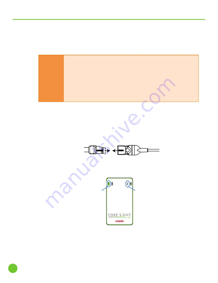
5.
Verify that the Channel ID indicator on the Preamp housing changes to green when the
Sensor is connected (Figure 19).
Figure 19:
Sensor connected to Channel 1
Channel 2 White indicator lit
(no Sensor connected)
Channel 1 Green indicator lit
(Sensor connected)
28
CAS Medical Systems, Inc.
Monitoring Essentials: Attaching Sensors to the Patient


