


8
the motor in this unit is capable of operating at the new operating
condition. Fan shaft loading increases dramatically as wheel
speed is increased.
To reduce vibration, replace the motor’s adjustable pitch pulley
with a fixed pitch pulley (after the final airflow balance adjust-
ment). This will reduce the amount of vibration generated by
the motor/belt-drive system.
To determine variable pitch pulley diameter, perform the fol-
lowing calculation:
1. Determine full open and full closed pulley diameter.
2. Subtract the full open diameter from the full closed diameter.
3. Divide that number by the number of pulley turns open
from full closed.
This number is the change in pitch datum per turn open.
EXAMPLE
• Pulley dimensions 2.9 to 3.9-in. (full close to full open)
• 3.9 – 2.9 = 1-in.
• 1 divided by 5 (turns from full close to full open)
• 0.2 change in pulley diameter per turn open
• 2.9 + 0.2 = 3.1-in. pulley diameter when pulley closed one
turn from full open
CONDENSER COIL SERVICE
Round Tube Plate Fin (RTPF) Condenser Coil
The condenser coil is fabricated with round copper hairpins
tubing and plate fins of various materials and coatings (see Ap-
pendix A to identify the materials provided in this unit). The
coil can be one-row or composite-type two-row. Composite
two-row coils are two single-row coils fabricated with a single
return bend end tubesheet.
Recommended Condenser Coil Maintenance
and Cleaning
Routine cleaning of coil surfaces is essential to maintain proper
operation of the unit. Elimination of contamination and remov-
al of harmful residues will greatly increase the life of the coil
and extend the life of the unit. The following maintenance and
cleaning procedures are recommended as part of the routine
maintenance activities to extend the life of the coil.
REMOVE SURFACE LOADED FIBERS
Surface loaded fibers or dirt should be removed with a vacuum
cleaner. If a vacuum cleaner is not available, a soft non-metal-
lic bristle brush can be used. In either case, the tool should be
applied in the direction of the fins. Coil surfaces can be easily
damaged (fin edges can be easily bent over and damage to the
coating of a protected coil) if the tool is applied across the fins.
NOTE: Use of a water stream, such as a garden hose, against a
surface loaded coil will drive the fibers and dirt into the coil. This
will make cleaning efforts more difficult. Surface loaded fibers
must be completely removed prior to using low velocity clean wa-
ter rinse.
PERIODIC CLEAN WATER RINSE
A periodic clean water rinse is very beneficial for coils that are
applied in coastal or industrial environments. However, it is
very important that the water rinse is made with a very low ve-
locity water stream to avoid damaging the fin edges. Monthly
cleaning, as described below, is recommended.
ROUTINE CLEANING OF COIL SURFACES
Periodic cleaning with Totaline
®
, environmentally sound coil
cleaner, is essential to extend the life of coils. This cleaner is
available from Carrier Replacement Components Division as
part number P902-0301 for a one gallon container, and part
number P902-0305 for a 5 gallon container. It is recommended
that all coils, including standard aluminum, pre-coated, copper/
copper or E-coated coils, be cleaned with the Totaline environ-
mentally sound coil cleaner as described below. Coil cleaning
should be part of the unit’s regularly scheduled maintenance
procedures to ensure long life of the coil. Failure to clean the
coils can result in reduced durability in the environment.
Avoid use of:
• coil brighteners
• acid cleaning prior to painting
• high pressure washers
• poor quality water for cleaning
Totaline environmentally sound coil cleaner is nonflammable,
hypoallergenic, non-bacterial, and a USDA accepted biode-
gradable agent that will not harm the coil or surrounding com-
ponents such as electrical wiring, painted metal surfaces, or in-
sulation. Use of non-recommended coil cleaners is strongly
discouraged since coil and unit durability could be affected.
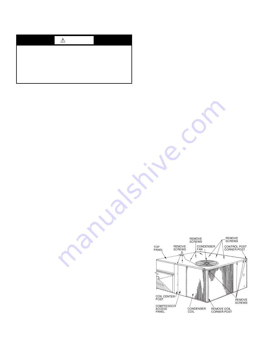
TWO-ROW COILS
Clean coil as follows:
1. Turn off unit power, tag disconnect.
2. Remove top panel screws on condenser end of unit.
3. Remove condenser coil corner post. (See Fig. 12.) To hold
top panel open, place coil corner post between top panel
4. Remove screws securing coil to compressor plate and
compressor access panel.
5. Remove fastener holding coil sections together at return
end of condenser coil. Carefully separate the outer coil
section 3-in. to 4-in. from the inner coil section. See
Fig. 13.
Fig. 12 — Cleaning Condenser Coil
CAUTION
EQUIPMENT DAMAGE HAZARD
Failure to follow this caution can result in equipment damage.
Drive packages cannot be changed in the field. For exam-
ple: a standard drive cannot be changed to a high static
drive. This type of change will alter the unit’s certification
and could require heavier wiring to support the higher am-
perage draw of the drive package.
Summary of Contents for WeatherMaster Puron 48HC D17
Page 18: ...18 COOLING CHARGING CHARTS Fig 22 Cooling Charging Chart 15 Ton ...
Page 19: ...19 Fig 23 Cooling Charging Chart 17 5 Ton ...
Page 20: ...20 Fig 24 Cooling Charging Chart 20 Ton ...
Page 21: ...21 Fig 25 Cooling Charging Chart 25 Ton ...
Page 37: ...37 Fig 48 Unit Control Box IGC Location IGC Board IGC Board Side view Front view ...
Page 40: ...40 Fig 51 Typical IGC Wiring Diagram ...
Page 46: ...46 Fig 57 RTU Open Overlay for Economizer Wiring ...
Page 47: ...47 Fig 58 VFD Overlay for W2770 Controller Wiring ...
Page 84: ...84 Fig B 48HC D17 D28 Control Diagram 208 230 3 60 460 575 3 60 ...
Page 85: ...85 Fig C 48HC D17 D28 Power Diagram 208 230 3 60 ...
Page 86: ...86 Fig D 48HC D17 D28 Power Diagram 460 3 60 ...
Page 87: ...87 Fig E 48HC D17 D28 Power Diagram 575 3 60 ...
Page 88: ...88 Fig F 48HC D17 D28 Control Diagram with Humidi MiZer System ...
Page 89: ...89 Fig G 48HC D17 D28 Power Diagram 208 230 3 60 with Humidi MiZer System ...
Page 90: ...90 Fig H 48HC D17 D28 Power Diagram 460 3 60 with Humidi MiZer System ...
Page 91: ...91 Fig I 48HC D17 D28 Power Diagram 575 3 60 with Humidi MiZer System ...
Page 92: ...92 Fig J PremierLink System Control Wiring Diagram 50HE500891 F ...
Page 93: ...93 Fig K PremierLink System Control Wiring Diagram with Humidi MiZer System ...
Page 94: ...94 Fig L RTU OPEN Wiring Diagram ...
Page 95: ...95 Fig M RTU OPEN Wiring Diagram with Humidi MiZer System ...
Page 97: ......