


6
NOTE: In order for the Display to receive alarms from a
CCN device, the CCN user interface bit in the device's Alarm
Routing decision must be set to 1.
START/STOP BUTTON – The Touch Pilot includes an
equipment Start/Stop Button that enables you to start or
stop the Chiller.
NOTE: This button is not functional when the Display is in
Network mode.
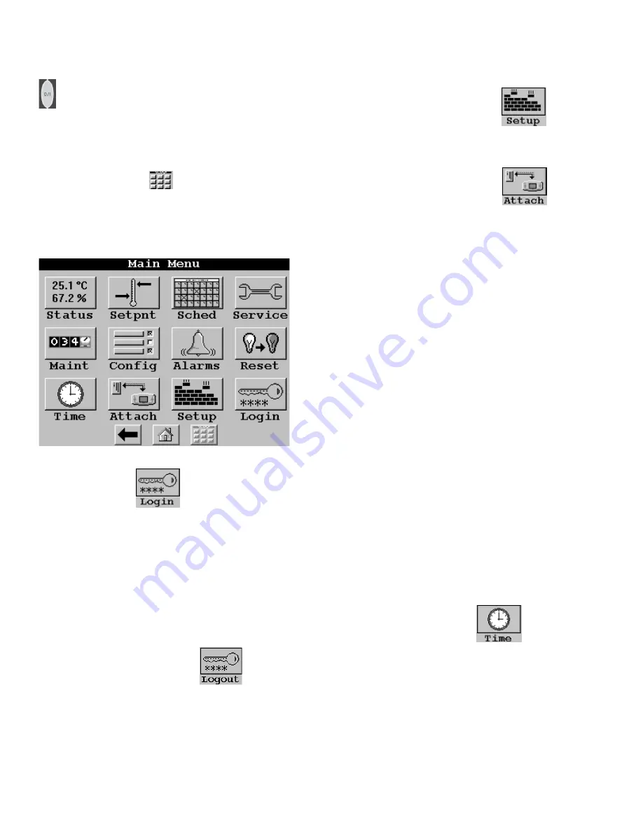
Main Menu –
Press the
button to display the Main
Menu as shown in Figure 10 below. An explanation of each
Main Menu option follows.
Figure 10 - Main Menu
LOGIN – Pressing the
button displays the Login
dialog box. Press the numbers to enter your four-digit pass-
word and press the OK button. Once you are logged in, the
LOGIN button will changed to LOGOUT, and the Display
will permit or restrict options corresponding to your access
level. Note that when you are logged out, you will have
read-only access. The Login dialog box will, however, be
displayed any time you are logged out and select an op-
tion/feature that requires Limited or Full Access levels. For
additional information on access levels, refer to SETUP in
the Main Menu section of this manual.
LOGOUT– Pressing the Main Menu's
button dis-
plays a confirmation message asking you to confirm the
request to logout. Note that whenever you are logged out,
read-only access is still permitted.
Inactivity Timeout Feature - If there is no contact with the
touch screen panel or the Equipment Start/Stop hardware
button for a 15 minute period, the Display will automati-
cally logout and return to the Default display without sav-
ing any changes. While the Display is performing an At-
tach process, however, the inactivity timeout feature will be
disabled.
SETUP – Pressing the Main Menu's
button
displays the Setup screen as shown in Figure 11, which is
displayed following this Main Menu section
.
ATTACH – Pressing the Main Menu's
button
will allow you to display the Attach list where you can
select an existing device or add a new device, and then
establish communication with the selected device. The At-
tach list consists of device name, bus and element num-
bers. The first entry in the Attach list (surrounded by two
**) is referred to as the Default device. It will be the device
to which the Display will automatically attach on power up.
The currently-attached device will be enclosed in angle
brackets (ex.: <<19XLCHR>>).
To Add a device to the Attach list: Add a new device to
the Attach list by pressing any Bus or Element button and
when prompted, entering the device's bus or element num-
ber.
To Attach to a device in the Attach list: Press the Name
button corresponding to the device to which you wish to
attach. You will then be presented with an Attach to this
device? confirmation message.
During the Attach process, the Display will upload all tables,
including any group displays, from the specified device.
On completion of a successful Attach, the Default display
will be shown. Note that the Inactivity Timeout feature will
be disabled while the Display is in the Attach process.
To Remove (reinitialize) an existing device from the At-
tach list: Modify the device's Bus and Element numbers to
zero and then touch the device's Name button.
To Clear (reinitialize) the entire Attach list: Press the
Clear the Controller List button, which is located immedi-
ately past the last device in the Attach list.
TIME – Pressing the Main Menu's
button while
in Network mode will allow you to change the attached
device’s time and date and holiday status. If the Display is
unattached, it will display its own time and date (if the time
has been set). If the Broadcast check box on the Time/Date
screen is selected, you will be prompted to broadcast time,
date, and holiday status to all CCN devices on the network
upon exiting the Time/Date screen.
Summary of Contents for Touch Pilot 33CNTPILOT
Page 2: ...ii ...


