background image

4

OPERATION

Power-Up Display –

 When the Touch Pilot is powered-

up it displays an Initialization progress bar and attaches
(initiates communication) to a controller that has been des-
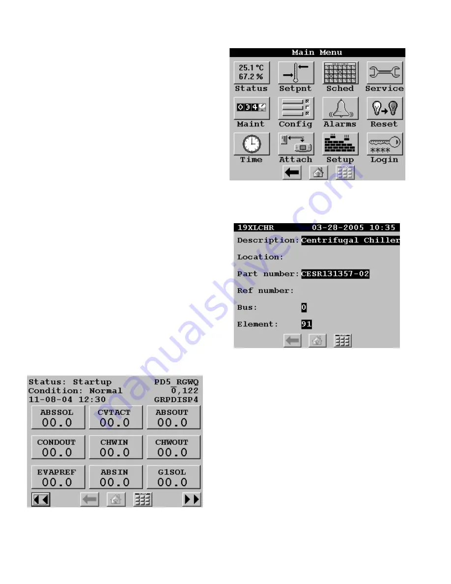
ignated as the Default device. The Touch Pilot then dis-
plays that controller's default Group Display (Figure 5), or if
the controller does not have Group Displays, displays that
controller's generic Controller Default Screen table. If a De-
fault device has not been specified, or if the Display cannot
communicate with it, the the Main Menu (Figure 6) will be
displayed on power-up.
NOTE:  Touching the screen anywhere for 5 seconds while
powering-up will promt you to restore contrast and calibra-
tion settings to factory defaults.
DEFAULT DEVICE DESIGNATION 

 The Default device is

the first entry in the Attach (Network Device) List. This list
is accessed using the Main Menu's Attach option. For ad-
ditional information, refer to Attach, which appears in the
Main Menu section of this manual.
DEFAULT GROUP DESIGNATION – The default group is
one of the attached controller's up to 8 group displays.
Group point complements default to factory-assigned
configurations in the specific CCN device, but are user-
modifiable from the Touch Pilot. Refer to Group Display,
which appears later in this manual. Currently, only the
30XA AQUAFORCE

TM

 chiller contains all 8 group displays.

Going forward, more Carrier equipment will support this

group functionality.

Following installation and initial power-up, the installer
should  Login and then select the Setup option from the
Main Menu to access the display's various setup and con-
figuration functions. Refer to Login and Setup, which ap-
pear in the Main Menu section of this manual.

Figure 5 - Example of a Group Display Screen

Figure 6 - Main Menu

Figure 7 - Example of a Generic Controller

Default Screen

Group Display Screen – 

The Touch Pilot supports up

to eight Group Display screens. A Group Display screen
shows status information and nine buttons that display the
first nine point names and values read from the attached
device. Each button displays the point name and the value.
If a point has an alarm, alert, or sensor failure, the point
button will be in inverse video. If there is a communication
failure with the attached device, all point buttons will be in
inverse video and the message Communication failure will
be displayed in the top left line of the screen. The bottom
line contains navigation buttons that allow you to move
between the Group Display screens. Refer to the Naviga-
tion and Operation Pushbuttons section of this manual for
additional information.

Pressing a point button will show the point's Point Data
dialog box (Figure 8 and 9). This box contains buttons that
allow you to remove the point from the group display, and
to apply or remove a force (point override).

Summary of Contents for Touch Pilot 33CNTPILOT

Page 1: ... 2 Decorative Bezel 2 Chiller Display Mounting 2 Operation 4 Power Up Display 4 Default Device Designation 4 Default Group Designation 4 Group Display Screen 4 To Remove a Point from a Group Display 5 To Add a Point to a Group Display 5 Navigation and Operation Pushbuttons 5 BACK 5 HOME 5 MAIN MENU 5 PREVIOUS 5 NEXT 5 OK 5 NO 5 CANCEL 5 CLEAR DATA 5 RESET DATA 5 ADD 5 REMOVE 5 INC DEC 5 SCROLL UP ...

Page 2: ...ii ...

Page 3: ... 24 Vac See Figure 2 on page 3 The power supply is 24 Vac at 60 Hz 15 10 VA minimum NOTE Do not run sensor or communication wiring in the same conduit with line voltage wiring Do not run 24 Vac wiring in the same multi conductor cable used for sensors or communications Perform the following steps to connect the power trans former 1 Install the field supplied transformer in an electrical en closure...

Page 4: ...e Figure 4 on page 3 The assembly will mount directly to the wall requiring only a small hole in the wall allowing the wiring connection to pass through Use four 8 x 1 5 in Phillips panhead screws and four wall anchors to fasten the Display to the wall DECORATIVE BEZEL A decorative bezel is supplied Af ter mounting and wiring the Display snap the decorative bezel on the Display to cover the mounti...

Page 5: ...Wiring 1 2 3 6 5 4 1 2 3 COMM GND 1000 FT MAXIMUM DRAIN WIRE TYP BLK TYP WHT TYP RED TYP BYPASS CONTROLLER ZONE CONTROLLER SYSTEM PILOT ZONE CONTROLLER BRIDGE RECOMMENDED 1 2 3 1 2 3 CCN CCN CCN CCN CHILLER DISPLAY Figure 3 Touch Pilot Bezel Figure 4 Touch Pilot Surface Mounting ...

Page 6: ...FORCETM chiller contains all 8 group displays Going forward more Carrier equipment will support this group functionality Following installation and initial power up the installer should Login and then select the Setup option from the Main Menu to access the display s various setup and con figuration functions Refer to Login and Setup which ap pear in the Main Menu section of this manual Figure 5 E...

Page 7: ...AIN MENU Displays the Main Menu screen A description of all Main Menu options can be found in the Main Menu section of this manual PREVIOUS In a group of sequential screens of the same type moves to the next earlier screen in the group NEXT In a group of sequential screens of the same type advances to the next screen in the group OK Agrees with or says yes to a prompt and performs the appropriate ...

Page 8: ...owing this Main Menu section ATTACH Pressing the Main Menu s button will allow you to display the Attach list where you can select an existing device or add a new device and then establish communication with the selected device The At tach list consists of device name bus and element num bers The first entry in the Attach list surrounded by two is referred to as the Default device It will be the d...

Page 9: ...able screen If the device has multiple tables of that type the Display will show a list of tables from which you can select the one you wish to access As you make changes to values in these tables the new values will be displayed On pressing a Navigation pushbutton to exit the current screen a confirmation mes sage will be displayed Pressing will save and down load the new values to the attached d...

Page 10: ... designation CONFIGURATION TABLES Display operation is controlled by decisions entered in the the following configuration tables which are accessible from a Carrier front end such as the Network Service Tool or ComfortVIEW CtlrID Controller Identification Configuration Table USERCONF User Configuration Table NOTE You should always perform an Upload to obtain the latest configuration before making ...

Page 11: ...Default Value 0 Network Settings Alarm Acknowledger Use this decision to specify whether the Touch Pilot will act as the alarm acknowledger for its CCN There must be only one alarm acknowledger per CCN Therefore if another CCN device such as ComfortVIEW the Autodial Gateway or TeLINK is already set as the Alarm Acknowledger for the CCN then this deci sion should be set to No NOTE The Display must ...

Page 12: ... Value blank Disable START STOP control Equipment Start Stop This decision is used in conjunc tion with the Display s Start Stop button Enter the CCN variable name of the equipment point to which the Start Stop output point is connected If you press the button while in equipment mode the Display will first look at the equipment point s status in accordance with the variable name you entered in the...

Reviews: