


9
another control function (example: Fire Shutdown) or by ser-
vice personnel in order to achieve an override or test function.
GAIN — A parameter or correction factor used in a control
loop calculation that adjusts the responsiveness and sensitivity
of the control loop.
Accessing the Control System (HSIO)
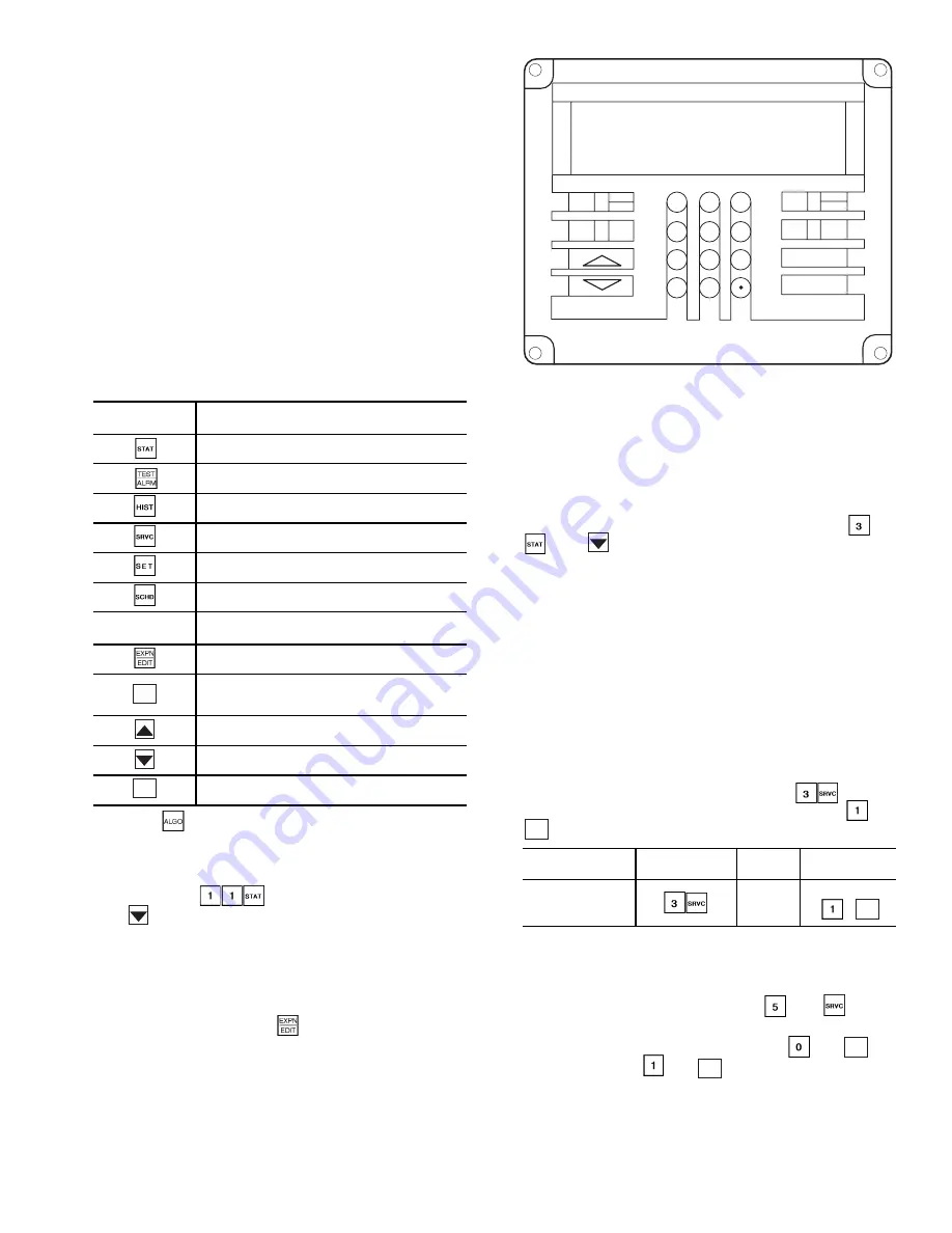
KEYPAD AND DISPLAY MODULE (HSIO) — The key-
pad and display module HSIO (human sensory input/output) is
a field-installed accessory. The HSIO provides unit function in-
formation at the unit. See Fig. 8. The module consists of a key-
pad with 6 function keys, 5 operative keys, 10 numeric keys
(0 through 9). The display is a 2-line, backlit, alpha-numeric
liquid crystal display (LCD). Each line of the LCD shall dis-
play up to 24 characters (with expanded scrolling display capa-
bility). The HSIO module contains an RJ-14 data cable connec-
tion for simple installation on unit or a remote site. Module is
powered by the 24-v control circuit of the unit. Key usage is
explained in Table 2. Each function has one or more subfunc-
tions as shown in Table 3.
Table 2 — HSIO Keypad Key Usage
NOTE: The
key is not used with these units.
STANDBY/RUN MODE — Unit operation is controlled by
the status of the run/standby mode on the HSIO. To access
the mode, press
on the HSIO keypad, and then
press
. The HSIO will display either STBY YES (unit in
standby mode) or STBY NO (unit in run status).
SUMMARY DISPLAY — Whenever the keypad has not
been used for 10 minutes, the display will automatically switch
to an alternating summary display. This display has 5 parts,
shown below, which alternate in continuous rotating sequence.
Display
Expansion
(Press)
TUE 12:45
TODAY IS TUE, TIME IS 12:45 PM
MODE 23
MODE IS UNOCCUPIED HEAT
COOL 1
COOLING STAGES 1
HEAT 1
HEATING STAGES 1
2 ALARMS
THERE ARE 2 ALARMS
ACCESSING FUNCTIONS AND SUBFUNCTIONS —
The functions and subfunctions are shown in Table 3. See
Table 4 for a procedure on how to access these functions.
OPERATING MODE DISPLAY — The operating mode
codes are displayed to indicate the operating status of the unit
at a given time. To enter the Modes subfunction, press
and
. Use
to determine if more than one mode is in effect.
See Table 5 for a list of the modes and mode names.
LOGON AND LOGOFF/PASSWORD — Password access
is required when entering any subfunction under the SERVICE
group. The user configuration inputs are located in the Service
subfunctions. To Log On, enter the password. When configura-
tion checks and changes are completed, enable the Data Reset
function and then Log Off. To log on to the Service function,
perform the actions in Table 6.
DATA RESET — Whenever a configuration in the Factory
Configuration group (Service function, Subfunction 3) has
been changed by the user or service person, it is necessary to
enable the Data Reset function before the control will recog-
nize these changes in configuration instructions. To enable
Data Reset, enter Data Reset by pressing
. Scroll
down until the HSIO displays the letters DTRS. Press
and
.
CHANGING DISPLAY FOR METRIC UNITS — To
change the display of the HSIO from English to Metric units,
enter Service subfunction 5 by pressing
and
. Scroll
down until the HSIO displays UNITS. Select desired units of
measure. To select Imperial (English), press
and
. To
select Metric, press
and
. See Table 7.
FUNCTION
KEYS
USE
Status — To display diagnostic codes and
current operating information about the unit.
Quick Test — To check inputs and outputs for
proper operation
History — To check most recent alarms.
Service — To enter specific unit configuration
information.
Set Point — To enter operating set points and
day/time information.
Schedule — To enter occupied/unoccupied
schedules for unit operation.
OPERATIVE
KEYS
USE
Expand Display — To display a non-abbrevi-
ated expansion of the display.
Clear — To clear the screen and return to pre-
vious display. Also used to enter data value of
zero.
Up Arrow — To return to previous display
position.
Down Arrow — To advance to next display
position.
To enter data.
CLEAR
ENTER
DESCRIPTION
HOW TO
CONFIGURE
SET
POINT
RANGE
Enable
Data Reset
DTRS
Select
,
ENTER
ENTER
ENTER
ENTER
1
2
3
4
5
6
7
8
9
0
-
STAT
SET
SCHD
EXPN
EDIT
SRVC
HIST
ALGO
TEST
ALRM
CLEAR
ENTER
Fig. 8 — Keypad and Display Module


