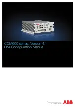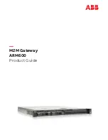
CRDMNDGW001A00
CRDMNDGW002A00
Energy Demand Gateway
Rooftop Unit Accessory
Installation Instructions
C13331
NOTE
: Read the entire instruction manual before starting the
installation, and follow instructions carefully. Failure to do so may
damage equipment, void warranties, or even cause serious injuries.
SAFETY CONSIDERATIONS
Improper installation, adjustment, alteration, service, maintenance,
or use can cause explosion, fire, electrical shock, or other
conditions which may cause death, personal injury or property
damage. Consult a qualified installer, service agency or your
distributor or branch for information or assistance. The qualified
installer or agency must use factory--authorized kits or accessories
when modifying this product. Refer to the individual instructions
packaged with the kits or accessories when installing.
Follow all safety codes. Wear safety glasses, protective clothing,
and work gloves. Have a fire extinguisher available. Read these
instructions thoroughly and follow all warnings and cautions
included in literature and attached to the unit. Consult local
building codes and the current edition of the National Electrical
Code (NEC) NFPA 70.
In Canada, refer to the current editions of the Canadian Electrical
Code CSA C22.1.
Recognize safety information. When you see this symbol
on
the unit and in instructions or manuals, be alert to the potential for
personal injury. Understand the signal words
DANGER
,
WARNING
, and
CAUTION
. These words are used with the
safety--alert symbol.
DANGER
identifies the most serious hazards,
which
will
result in severe personal injury or death.
WARNING
signifies hazards, which
could
result in personal injury or death.
CAUTION
is used to identify unsafe practices, which
may
result
in minor personal injury or product and property damage.
NOTE
is used to highlight suggestions which
will
result in enhanced
installation, reliability, or operation.
INTRODUCTION
Carrier
r
’s Energy Demand System provides reliable and
automated processes to manage the costs of energy consumption.
Carrier’s Energy Demand System uses wireless devices
incorporating patented Swarm Energy Management algorithms to
create a network of coordinated rooftop units to reduce and
optimize their energy usage.
This system creates a wireless
network of rooftop units with Energy Demand Load Controllers
communicating through the Energy Demand Gateway.
Each individual Load Controller can independently decide whether
it should allow its unit to run by a relay that can break the
connection between the rooftop unit and the thermostat. By
communicating energy information through the Gateway, units are
prevented from running simultaneously when it is not necessary,
thereby smoothing out peak demand over time. This method
provides the ability to accomplish Demand Management, Demand
Response, and energy trending over time.
Carrier offers two accessories that, when combined, make up the
Energy Demand System. This technology utilizes Swarm Energy
Management
t
methodology as a basis for the operating sequence:
S
Energy Management Gateway (Coordinator)
(Model Nos. CRDMNDGW001A00, CRDMNDGW002A00):
This model is packaged with a cellular modem and modem
enclosure, and is the first controller to be attached to a packaged
rooftop unit and powered up. This controller will both
monitor/control the attached rooftop unit, as well as act as a
communications gateway back to the Swarm Energy
Management Web Portal, a service provided by REGEN Energy,
Inc..
Table 1 – Kit Voltage Requirements
Kit No.
Unit Voltage
CRDMNDGW001A00
208/230/460V
CRDMNDGW002A00
575V
S
Energy Demand Load Controller
(Model Nos. CRDMNDMD001A00, CRDMNDMD002A00):
This load controller is installed on the remaining packaged
rooftop units that are to be monitored and controlled.
NOTE
:
Please ensure you have the correct Installation
Instructions for the given type of controller before continuing.
INSTALLATION CONSIDERATIONS
RTU Checklist
Toward the end of this document, there is a RTU checklist that
must be filled out for every Gateway (Coordinator) installed. The
RTU checklist must be legible.
The RTU checklists need to be
scanned and emailed to [email protected] within 48
hours of the completion of the installation.
Providing this
checklist is vital to completing device set--up for operation.


