31
Check Motor Rotation
1. Close the starter enclosure door.
2. Apply 3-phase power to drive.
3. The VFD checks for proper phase rotation as soon as power
is applied to the starter and the PIC6 controls power up.
4. An alarm message will appear on the HMI screen if the
phase rotation is incorrect. If this occurs reverse any 2 of
the 3 incoming power leads to the starter and reapply
power. The motor is now ready for a rotation check.
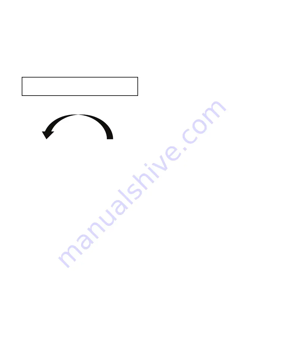
5. When the VFD is energized and the motor begins to turn,
check for counterclockwise motor rotation through second
stage sight glasses. See Fig. 34.
Fig. 34 — Correct Motor Rotation
To Prevent Accidental Start-Up
A
chiller STOP override setting may be entered to prevent acci-
dental start-up during service or whenever necessary. From the
Main Menu, access the General Parameters Menu and use the
down arrow to reach Stop Override on the GENUNIT table.
Change Stop Override to Yes; then execute the command by
touching the lightning button. The message “ALM-276 Protective
Limit - Stop Override” will appear in the Home Screen message
area. To restart the chiller, access the same screen and change the
Stop Override option to No.
Check Chiller Operating Condition
Check to be sure that chiller temperatures, pressures, water flows,
and refrigerant levels indicate the system is functioning properly.
Instruct the Customer Operator(s)
Ensure the operator understands all operating and maintenance
procedures. Point out the various chiller parts and explain their
function as part of the complete system.
EVAPORATOR-CONDENSER
Relief devices, refrigerant charging valve, temperature sensor lo-
cations, pressure transducer locations, condenser liquid level sen-
sor, main EXV, Schrader fittings, waterboxes and tubes, and vents
and drains.
MOTOR COMPRESSOR ASSEMBLY
Guide vane actuator, transmission, motor cooling system, tem-
perature and pressure sensors, sight glasses, motor temperature
sensors, MBC, and compressor serviceability.
ECONOMIZER
BPHX and economizer EXV. Pressure transducer and temperature
sensor location.
CONTROL SYSTEM
NETWORK and LOCAL start, reset, menu, softkey functions,
HMI operation, occupancy schedule, set points, safety controls,
and auxiliary and optional controls.
AUXILIARY EQUIPMENT
Starters and disconnects, separate electrical sources, pumps, and
cooling tower.
DESCRIBE CHILLER CYCLES
Refrigerant, motor cooling, and liquid reclaim.
REVIEW MAINTENANCE
Scheduled, routine, and extended shutdowns, importance of a log
sheet, importance of water treatment and tube cleaning, and im-
portance of maintaining a leak-free chiller.
SAFETY DEVICES AND PROCEDURES
Electrical disconnects, relief device inspection, and handling
refrigerant.
CHECK OPERATOR KNOWLEDGE
Start, stop, and shutdown procedures, safety and operating con-
trols, refrigerant charging, and job safety.
REVIEW MANUALS
Refer to the Start-Up, Operation, and Maintenance Manual and
the Controls, Operation and Trouble-shooting Manual..
OPERATING INSTRUCTIONS
Operator Duties
1. Become familiar with the chiller and related equipment
before operating the chiller.
2. Prepare the system for start-up, start and stop the chiller,
and place the system in a shutdown condition.
3. Maintain a log of operating conditions and document any
abnormal readings.
4. Inspect the equipment, make routine adjustments, and per-
form a Control Test. Maintain the proper refrigerant levels.
5. Protect the system from damage during shutdown periods.
6. Maintain set point, time schedules, and other PIC functions.
Prepare the Chiller for Start-Up
Follow the steps described in the Initial Start-Up section, page 30.
To Start the Chiller
1. Start the water pumps, if they are not automatic.
2. Press the Start/Stop icon on the HMI home screen to start
the system. If the chiller is in the OCCUPIED mode and
the start timers have expired, the start sequence will start.
Follow the procedure described in the Start-Up/Shutdown/
Recycle Sequence section, page 12.
Check the Running System
After the compressor starts, the operator should monitor the dis-
play and observe the parameters for normal operating conditions:
1. The moisture indicator sight glass on the refrigerant motor
cooling line should indicate single phase refrigerant flow and
a dry condition.
2. The condenser pressure and temperature varies with the
chiller design conditions. Typically the pressure will range
from 60 to 135 psig (390 to 950 kPa). with a correspond-
ing temperature range of 60 to 105°F (15 to 41°C). The
condenser entering water temperature should be controlled
below the specified design entering water temperature to
save on compressor kilowatt requirements.
IMPORTANT: Do not check motor rotation during coastdown.
Rotation may have reversed during equalization of vessel
pressures.
CORRECT MOTOR ROTATION
IS COUNTER-CLOCKWISE
WHEN VIEWED THROUGH THE
2ND STAGE SIGHT GLASS
TO CHECK ROTATION, ENERGIZE COMPRESSOR MOTOR MOMENTARILY.
DO NOT LET MACHINE DEVELOP CONDENSER PRESSURE.
CHECK ROTATION IMMEDIATELY.
ALLOWING CONDENSER PRESSURE TO BUILD OR CHECKING
ROTATION WHILE MACHINE COASTS DOWN MAY GIVE A FALSE
INDICATION DUE TO GAS PRESSURE EQUALIZING THROUGH COMPRESSOR.
RO
TATIO
N
Summary of Contents for AquaEdge 19MV
Page 49: ...49 Fig 46 SIOB...
Page 50: ...50 Fig 47 IOB2...
Page 51: ...51 Fig 48 19MV Auxiliary Controls Wiring...


