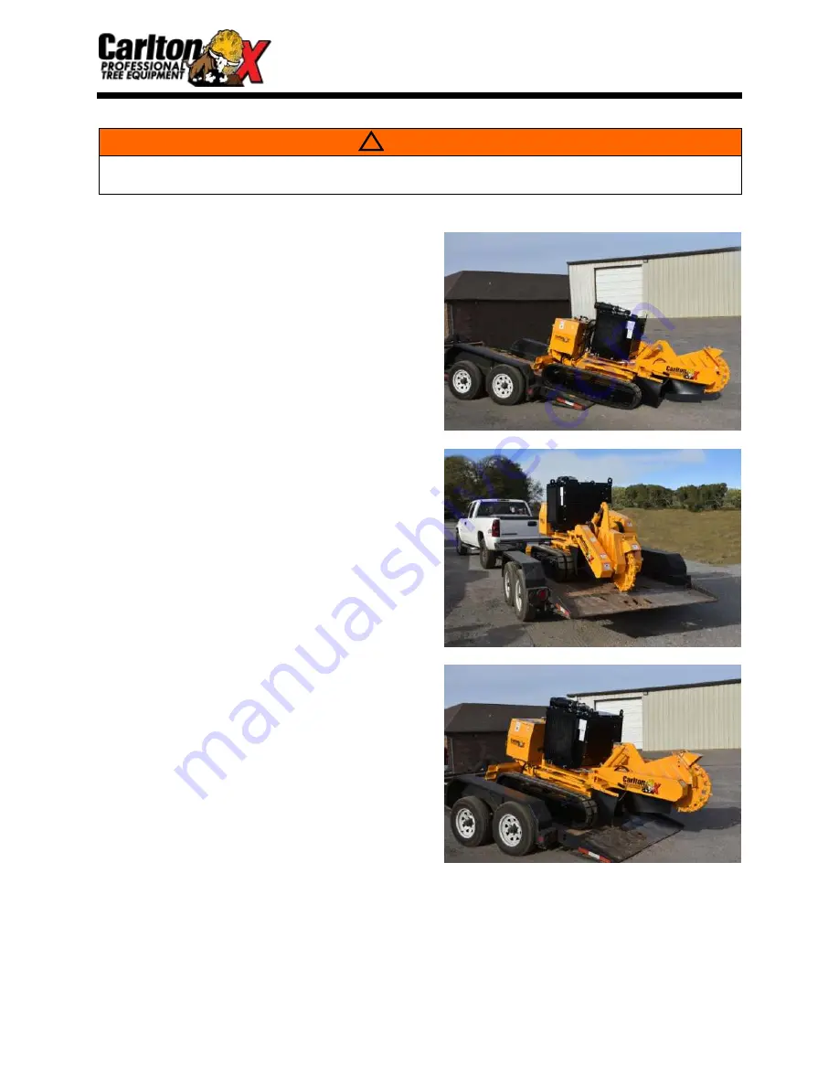
Carlton SP8018 Owner'S Manual Download Page 30

  SP8018                                     TRANSPORTING


LOADING 


Start engine as recommended by the 
engine manufacturers manual. 


Increase engine RPM, raise cutter head 
just off the ground. 


With operator in position, push the 
forward travel control lever and steer 
machine slowly up appropriate ramp into 
transport vehicle.


KEEP MACHINE AS LEVEL AS 

POSSIBLE. 


Continually adjust cutter head height as 
you go, keeping the mass as low to the 
ground as possible. 


Once the machine is loaded, lower the 
cutter head, shut down engine and secure 
machine tightly with sufficient tie downs 
to prevent any movement in transit. 


UNLOADING 


Undo tie down straps and check ramps 
for sturdiness and positioning.


Start engine, increase RPM, and raise 
cutter head to just clear deck and/or 
ramp.


Continually adjust Cutter head up and 
down to keep the center of gravity as 
low as possible. 


Proceed to work site using extreme 
caution on hills or uneven terrain.


WARNING


Trailer must be securely attached to tow vehicle before loading or unloading the stump grinder. 

Do not unload on anything other than level ground! 

17

Summary of Contents for SP8018

Page 1: ..._______ Engine Serial _____________ Purchase Date _____________ Dealer _____________ REVISION 220902 1 J P Carlton Company Div D A F Inc 121 John Dodd Road Spartanburg SC 29303 Ph 864 578 9335 Fax 864...

Page 2: ...BLANK SHEET...

Page 3: ...this product Gasoline or Diesel and the products of combustion of such fuels can expose you to chemicals including benzene which is known to the State of California to cause cancer birth defects or o...

Page 4: ...SP8018 SAFETY ALERT...

Page 5: ...SP8018 SAFETY ALERT OPERATE MACHINE FROM 25 FEET AWAY KEEP SPECTATORS AWAY...

Page 6: ...SP8018 SAFETY ALERT...

Page 7: ...SP8018 SAFETY ALERT...

Page 8: ...BLANK SHEET...

Page 9: ...arlton Co Inc will not be liable for consequential damages resulting from breach of warranty IT IS NECESSARY TO RETURN THE WARRANTY VALIDATION FORM AND NOTIFY J P CARLTON CO INC IN WRITING WITHIN TEN...

Page 10: ...the customers responsibility to deliver machine to dealers facility unless other arrangements have been agreed to between the selling dealer and the customer The manufacturer may elect at its discret...

Page 11: ...to stop machine and remove key before performing any type of maintenance 4 ______ Customer has been warned not to operate the machine without the cutter wheel guard in place 5 ______ Customer has bee...

Page 12: ...BLANK SHEET...

Page 13: ...AILY CHECKLIST 9 MACHINE CONTROLS 10 TRANSPORTING 16 MACHINE OPERATION 18 MAINTENANCE MACHINE MAINTENANCE 23 TROUBLESHOOTING GUIDE 29 SERVICING CUTTER WHEEL 31 SERVICING BELTS 36 SERVICING BEARINGS 46...

Page 14: ...e it Slowly experiment with the controls and gradually work yourself up to the full capabilities of this machine The Carlton Model SP8018 is a durable and profitable professional stump grinder Read th...

Page 15: ...models without any prior notification or obligation Inspect your new Carlton Stump Grinder as soon as you receive it Any damages incurred during shipment are not warranted and therefore not covered r...

Page 16: ...nders Heavy construction Tapered roller bearings on cutter wheel jackshaft 1 1 2 thick Blanchard ground cutter wheel Low maintenance drive belt Carbide tipped cutter teeth Standard Cutter Wheel 48 tee...

Page 17: ...th 166 421 6 cm Width 60 152 4 cm Height 83 210 8 cm Cutting Depth 18 45 72 cm Cutting Height 43 109 22 cm Cutting Swing 80 203 2 cm Number of Teeth on Cutter Wheel 76 Razor Wheel 48 Standard Wheel Cu...

Page 18: ...his symbol The Safety Alert Symbol will be accompanied by one of the following words DANGER WARNING or CAUTION A DANGER symbol means that if the instructions are not followed the possibility of seriou...

Page 19: ...n while running or during transport DO NOT move position or transport this machine while cutter wheel is engaged DO NOT operate any machinery while under the influence of alcohol or drugs prescription...

Page 20: ...Never leave the controls unattended while in operation Be sure machine is not capable of operation when left unattended Stop engine and remove key when repairing or adjusting machine or drive belts Ke...

Page 21: ...s it susceptible to tipping over sideways Overturning this machine can result in personal injury property damage and or seizing the engine While in transit positioning the cutter wheel uphill and as c...

Page 22: ...part numbers Check fuel filter for debris or water Replenish fuel tank with fresh fuel Check condition and tightness of drive belts See Maintenance Section New belts will stretch and become loose as...

Page 23: ...Remote This switch operates only the left track drive motor Use both controls in the same direction FWD FWD or REV REV to move machine forward or reverse The radio transmitter also has a single switc...

Page 24: ...gh engine speeds Close the valve by turning clockwise to allow the cutter wheel to move side to side at low engine speed GROUND SPEED ADJUSTMENT VALVE Located on the side of the control panel this val...

Page 25: ...r specific controls operation and service Emergency Stop Button E STOP On a HATOX remote Twist E stop to activate remote On an OMNEX remote Press button then toggle any switch on the remote to activat...

Page 26: ...crews in the junction box lid Then remove the circuit panel by unlatching the plastic tabs on either side of the receiver housing The receiver panel will now slide out of the cap Note you may need to...

Page 27: ...n twisting the E STOP button clockwise to turn remote on then release Both indicator lights should be on Turn the machine key switch to the on run position to activate the transmitter This begins the...

Page 28: ...ion key switch to the on position To shut off the engine return the On Off switch to the Off position Refer to Machine Operations Section of manual for startup and shutdown procedures Ignition Switch...

Page 29: ...fer all around LOADING RAMPS MUST BE STURDY AND ATTACHED TO THE TRANSPORT VEHICLE BEFORE ATTEMPTING TO LOAD UNLOAD THIS MACHINE TRAILER MUST BE SECURELY ATTACHED TO TOW VEHICLE BEFORE LOADING OR UNLOA...

Page 30: ...machine is loaded lower the cutter head shut down engine and secure machine tightly with sufficient tie downs to prevent any movement in transit UNLOADING Undo tie down straps and check ramps for stu...

Page 31: ...ut a remote set the On Off switch to the Machine On position and follow Start Engine process The FLOW High Low selector switch and the GEAR High Low selector switch located on the side of the control...

Page 32: ...r is operating there is a yellow ACTIVE light that will be flashing the light is indicated in the picture at the right Read the radio control manual for more information on the meaning of different li...

Page 33: ...he transmitter is still on and restart the engine by turning the key If you lose the connection light off repeat the procedure from the beginning and perform each step exactly as described Start engin...

Page 34: ...g speed should be adjusted to a rate that will allow cutter wheel to pass through stump smoothly If jerking bouncing or significant drops in engine speed occur swing rate is too rapid and must be decr...

Page 35: ...tioning machine to work at best advantages Raise cutter wheel clear of stump and return to center position Reduce engine speed to idle DO NOT TURN OFF MOTOR Engine must be allowed to cool slowly at id...

Page 36: ...n dry cloth to wipe down the inside of the air cleaner housing and cover Check the general condition of the air cleaner housing and components Make sure there are no dents cracks or other damage to th...

Page 37: ...1 2 between the coolant and the bottom of the filler pipe Anti freeze ratio to water must be 50 50 never use 100 anti freeze Clean the coolant filler cap and check the caps gaskets for damage Replace...

Page 38: ...clean the area around the fuel filter before removing any parts do not take a chance on contaminating the fuel line Do not leave spilled fuel on the machine spilled fuel on hot engine parts can cause...

Page 39: ...haft bearings for tightness Weekly NOTE to access the jackshaft bearings you will need to remove the jackshaft cover Check setscrews in cutter wheel bearings for tightness Weekly Clean out Poly Chain...

Page 40: ...ce and tighten cap Note This machine is filled with Citgo AW32 hydraulic oil at the time of manufacture Refill with the same or equivalent oil Inspect hydraulic hoses and fittings for leaks tightness...

Page 41: ...rade 2 grease or equivalent Always clean tip of grease gun fitting and grease fitting on machine before attaching hose to prevent dirt from being forced into machine parts Note Wipe off excess grease...

Page 42: ...tension too loose Belt out of alignment Tighten Align Pulleys Belt jumping off Engaging or disengaging belt at high engine RPM Belt keeper too far from belt Belt worn Pulley worn Only engage or diseng...

Page 43: ...tighten bolts Replace bearings Bearing will not take grease Grease fitting clogged Replace fitting Machine will not operate with remote On Off switch on control panel is not in the Remote On position...

Page 44: ...th to this edge with gauge against pocket not against cutter wheel All teeth are set 1 1 4 out of the pocket to the edge of the carbide DANGER More accidents occur while performing maintenance than an...

Page 45: ...ts of teeth to cancel vibration Straight teeth are mounted in TWO OPPOSING OUTSIDE POCKETS A straight tooth must have a 45 tooth accompanying it in the same pocket set The opposite pocket set should h...

Page 46: ...pin will need to be removed and reinserted as wheel is rotated to change remaining teeth The teeth do not require a setting gauge The only requirement is to be installed in the proper direction and t...

Page 47: ...the corner and this will turn the opposite corner out for use These teeth are tightened with nuts Torque on nuts is not to exceed 170 ft lbs All teeth on cutter wheel sides are Plow Bolt Bits When ch...

Page 48: ...ll hit the stump instead of the carbide thus causing a lot of vibration Once the shank is angled far enough back then begin sharpening carbide Cut shank with a standard rock and cut carbide with a sil...

Page 49: ...ice used you can check belt tension through the slot on the belt guard or you may need to remove the belt guard cover DANGER More accidents occur while performing maintenance than any other time Use e...

Page 50: ...o tight It is important to maintain the proper belt tension for optimal performance Make needed adjustments to maintain the recommended belt tension See next section for how to Adjust Belt Tension NOT...

Page 51: ...ts at a time and recheck tension Make equal adjustments to both eyebolts to keep sheaves aligned Keep making slight adjustments and recheck tension until correct tension is achieved To loosen belt ten...

Page 52: ...am bolts and slide the bearing shaft by tightening both jam bolts equally To loosen belt tension loosen the two bolts securing each cutter wheel bearing both sides Next loosen the inside jam nut on bo...

Page 53: ...t to being dished or concave Therefore worn sheaves dramatically reduce the efficiency of the drive VISUAL CUES The worst sheave wear will be a highly polished track in the sheave wall deep enough tha...

Page 54: ...me procedure only in reverse Never pry new belts onto the sheave Adjust jam nuts evenly and equally until belt starts getting tight then check tension Check sheave alignment and make adjustments using...

Page 55: ...ock load In a shock load failure the fibers are broken and over a period of time the belt will break down from the shock load and snap in half A broken belt with lost teeth indicates that the belt was...

Page 56: ...on the cutter wheel bearings to adjust proper tension on the belt making sure to tighten or loosen them equally keeping the sprockets aligned Use a straight edge to check sprocket alignment after adj...

Page 57: ...tion of bushing on shaft before removing for lining up bushing when replaced Remove belts as described in Replacing Belts section Remove bolts from the bushing and screw each bolt into the threaded ho...

Page 58: ...ighten until bushing is at the location marked on the shaft earlier Go to Replacing Belts section to replace belts and adjust tension Make sure sheaves are aligned when retightening belts to the prope...

Page 59: ...G LIFE CUTTER WHEEL BEARINGS There are two 2 bearings on the cutter wheel shaft These bearings should be purged using grease EVERYDAY Purge until new grease is seen to keep dirt and moisture out PROPE...

Page 60: ...urns to coat all surfaces with fresh grease Also inspect seals making certain that they are in proper position in grooves and intact Check tightness of mounting bolts and retighten if needed Be alert...

Page 61: ...ulic oil every 500 hours of operation or at least once a year depending on use Flush the hydraulic tank when changing the hydraulic oil Replace oil if it is very dark contaminated has a burnt odor or...

Page 62: ...hing down into position displacing the old bushing Swing cylinder back into position Re install rod end to main frame using new pin assemblies REPLACING HYDRAULIC HOSES Place cutter wheel on ground be...

Page 63: ...go on and off as the temperature of the oil fluctuates Keep oil cooler fins clean Use a garden hose and a mild detergent CAUTION Do Not use a power washer as it may cause the fins to bend Do Not use a...

Page 64: ...The clutch is disengaged All machine parts have come to a complete stop All machine parts have had sufficient time to cool down No operator is in position at the controls to accidentally start machine...

Page 65: ...ing at 200 F 93 3 C Carlton uses TEXACO STARPLEX II grease Listed below are the manufacturer s suggested guidelines for lubrication 1 The PTO bearing should be lubricated after each 50 hours of operat...

Page 66: ...SP8018 STEIN MFG PTO CLUTCH Depending on engine selection 53...

Page 67: ...Lock Bushing Installation and Removal To Install TAPER LOCK Type Bushings 1 Clean the shaft bore of bushing outside of bushing and the sprocket sheave hub bore of all oil paint and dirt File away any...

Page 68: ...specified in Table 1 below Taper Lock Bushings Bushing Bolts Torque Wrench Style Qty Size lb ft lb in 1008 2 1 4 20 x 1 2 4 6 55 1108 2 1 4 20 x 1 2 4 6 55 1210 2 3 8 16 x 5 8 14 6 175 1610 2 3 8 16 x...

Page 69: ...t bushing bore outside of bushing and the sprocket sheave hub bore of all oil paint and dirt File away any burrs Note Do not lubricate the bushing taper hub taper bushing bore or the shaft Doing so ma...

Page 70: ...Style Qty Size lb ft lb in H 2 1 4 x 3 4 7 9 95 JA 3 10 24 x 1 4 5 54 SH SDS 3 1 4 20 x 1 3 8 9 0 108 SD 3 1 4 20 x 1 7 8 9 0 108 SK 3 5 16 18 x 2 15 0 180 SF 3 3 8 16 x 2 30 0 360 E 3 1 2 13 x 2 3 4...

Page 71: ...1 RUBBER TRACK OPERATIONS MANUAL...

Page 72: ...2...

Page 73: ...s It is important not to carry out modifications to the track system which could compromise proper operation and safety Manufacturer is not responsible for any injury or damage caused by unauthorized...

Page 74: ...e hoist has an adequate load rating The below image demonstrates a track system being safely lifted with slings The belt lugs prevent the belt from slipping for this reason choker chains are not neces...

Page 75: ...free from debris before moving the machine Make certain the tracks are not frozen to the ground before moving the machine Ensure no leakage of oil from gearbox roller and idler before and during track...

Page 76: ...ct with sharp edges particularly sharp concrete edges This point loads the track and can cause damage to the internal steel cords in the belt 5 Rubber track systems are designed to be used on smooth s...

Page 77: ...aulic system since oil may be very hot when the machine has just been working Use only supplied approved replacement parts Use of unapproved parts will invalidate the warranty Dispose of lubricants in...

Page 78: ...mmediately tighten bolts and nuts to correct torque as per Appendix A replace damaged or worn components and refill the oil to recommended levels WARNING DO NOT operate the tracks with damaged or defe...

Page 79: ...ack as shown below The above conditions must be fulfilled on any new track system This must also be regularly checked and corrected where necessary by adding grease to the grease tensioner as describe...

Page 80: ...ease chamber tightening the track If this valve is loosened grease will escape causing the track to de tension Shown is a typical idler and tensioner assembly used on the rubber track system This is s...

Page 81: ...n the grease fitting by turning in a counterclockwise direction using gradual increments until the grease begins to be expelled Care must be taken not to loosen the grease fitting too quickly When the...

Page 82: ...counterclockwise If the grease does not start to drain out then slowly rotating the track can help Insert steel tubes as shown and slowly rotate the track in reverse This draws the tubes between the i...

Page 83: ...the valve and slowly apply grease The Idler will gradually move out to its working position 5 Set to the correct tension using the test methods mentioned in section 2 3 6 Clean off any loose grease a...

Page 84: ...e level indicated To drain track the machine until a plug is at 6 o clock position as shown below Unscrew both plugs and allow all oil to discharge into a suitable container Dispose of waste oil in a...

Page 85: ...15 2 6 LUBRICATION CHART...

Page 86: ...ENERAL COMPONENTS Item Part No Description Quantity 1 ROLLER NUT 2 SPRING WASHER 3 WASHER 4 ROLLER 5 SPROCKET 6 GEARBOX MOTOR 7 FRAME 8 DRIVE COVER PLATE 9 RUBBER BELT 10 TENSIONER COVER 11 TENSIONER...

Page 87: ...uld be replaced immediately to prevent damage to the system 3 3 WEAR LIMITS To ensure the most economical use of the track systems it is important to determine the appropriate time to replace each of...

Page 88: ...tensioner access plate removed see Section 2 4 1 make a visual inspection of the greaser looking for any signs of leaking grease Possible Cause If grease is leaking from the base of the greaser where...

Page 89: ...values of flow and pressure passing to the hydraulic motors is less than that required to drive the tracks see machine manufacturer s separate publication there may be a fault in the machine hydrauli...

Page 90: ...entified by a plug situated on the outer face of the gearbox end cover shown fig 1 above 1 Unscrew the disengagement plug from the end cover with a male hex head wrench 2 Use appropriate size TYP M6x5...

Page 91: ...being supplied to the motors is different from one another the machine hydraulic pressure and flow settings may need to be adjusted Check 2 Test to ensure a pressure is being applied to the brake rele...

Page 92: ...22 APPENDIX A BOLT TORQUE TABLE...

Page 93: ...Appendix A...

Page 94: ...BLANK SHEET...

Page 95: ...working at its best Your authorized J P Carlton dealer knows your local conditions and is ready to deliver fast professional and expert service and or parts when you need it most Visit our website to...

Page 96: ......

Reviews: