


ENG
“EVD Evolution TWIN” +0300006EN - rel. 2.6 - 31.01.2019
32
C
ontrol
The control request for each driver can be received, respectively, by the closing
of digital input 1 or 2, via the network (LAN). The solenoid or the compressor
are activated when the valve, following the pre-positioning procedure, has
reached the calculated position. The following figure represents the sequence
of events for starting control of the refrigeration unit.
C
ontrol delay after defrost
Some types of refrigerating cabinets have problems controlling the electronic
valve in the operating phase after a defrost. In this period (10 to 20 min
after defrosting), the superheat measurement may be altered by the high
temperature of the copper pipes and the air, causing excessive opening of
the electronic valve for extended periods, in which there is return of liquid to
the compressors that is not detected by the probes connected to the driver.
In addition, the accumulation of refrigerant in the evaporator in this phase
is difficult to dissipate in a short time, even after the probes have started to
correctly measure the presence of liquid (superheat value low or null).
The driver can receive information on the defrost phase in progress, via the
digital input. The “Start delay after defrost” parameter is used to set a delay
when control resumes so as to overcome this problem. During this delay,
the valve will remain in the pre-positioning point, while all the normal probe
alarm procedures, etc. are managed.
Parameter/description
Def.
Min.
Max.
UOM
CONTROL
Start delay after defrost
10
0
60
min
Tab. 6.k
Important:
if the superheat temperature should fall below the set
point, control resumes even if the delay has not yet elapsed.
t
t
t
t
OFF
ON
R
OFF
ON
P
OFF
ON
S
OFF
ON
A
T1
T
2
W
Fig. 6.d
Key:
A
Control request
W
Wait
S
Standby
T1
Pre-position time
P
Pre-positioning
T2
Start delay after defrost
R
Control
t
Time
P
ositioning (change cooling capacity)
This control status is only valid for the pLAN controller.
If there is a change in unit cooling capacity of at least 10%, sent from the pCO
via the pLAN, the valve is positioned proportionally. In practice, this involves
repositioning starting from the current position in proportion to how much
the cooling capacity of the unit has increased or decreased in percentage
terms. When the calculated position has been reached, regardless of the time
taken (this varies according to the type of valve and the position), there is a
constant 5 second delay before the actual control phase starts.
Note:
if information is not available on the variation in unit cooling
capacity, this will always be considered as operating at 100% and therefore
the procedure will never be used. In this case, the PID control must be
more reactive (see the chapter on Control) so as to react promptly to
variations in load that are not communicated to the driver.
t
t
t
t
OFF
ON
R
OFF
ON
NP
OFF
ON
C
OFF
ON
A
T3
W
Fig. 6.e
Key:
A
Control request
T3
Repositioning time
C
Change capacity
W
Wait
NP
Repositioning
t
Time
R
Control
S
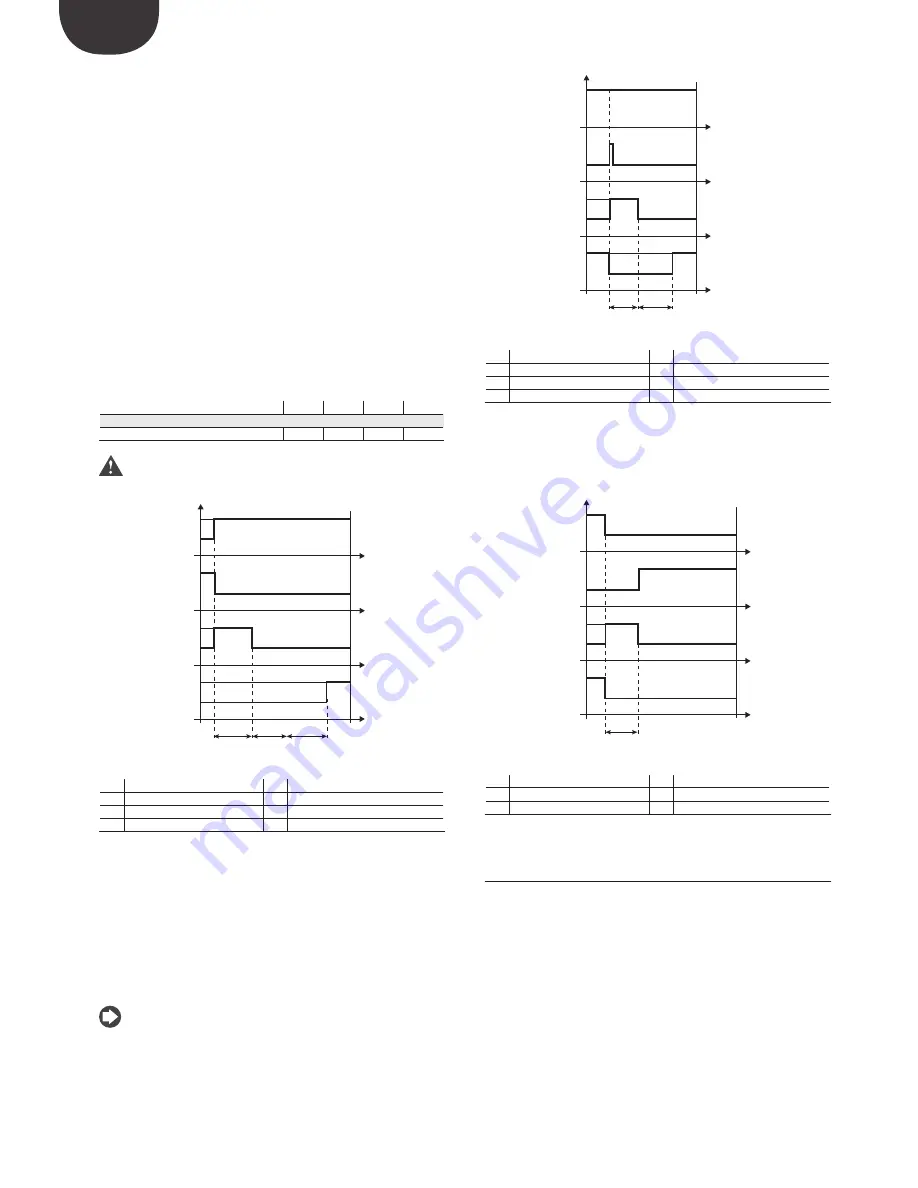
top/end control
The stop procedure involves closing the valve from the current position until
reaching 0 steps, plus a further number of steps so as to guarantee complete
closing. Following the stop phase, the valve returns to standby.
t
t
t
t
OFF
ON
R
OFF
ON
S
T
OFF
ON
S
OFF
ON
A
T4
Fig. 6.f
Key:
A
Control request
R
Control
S
Standby
T4
Stop position time
ST
Stop
t
Time
6.6 Special control status
As well as normal control status, the driver can have 3 special types of status
related to specific functions:
•
manual positioning:
this is used to interrupt control so as to move the
valve, setting the desired position;
•
recover physical valve position:
recover physical valve steps when fully
opened or closed;
•
unblock valve:
forced valve movement if the driver considers it to be
blocked.
Summary of Contents for EVD Evolution Twin
Page 2: ......
Page 4: ......
Page 6: ......
Page 66: ...ENG EVD Evolution TWIN 0300006EN rel 2 6 31 01 2019 66 Note...
Page 67: ......


