Carel EVD Evolution Twin User Manual Download Page 22

ENG

“EVD Evolution TWIN” +0300006EN - rel. 2.6 - 31.01.2019

22

Note that control is calculated as the sum of three separate contributions: 
proportional, integral and derivative.

• 

the proportional action opens or closes the valve proportionally to the 
variation in the superheat temperature. Thus the greater the K  (proportional 
gain) the higher the response speed of the valve. The proportional action 
does not consider the superheat set point, but rather only reacts to 
variations. Therefore if the superheat value does not vary significantly, the 
valve will essentially remain stationary and the set point cannot be reached;

• 

the integral action is linked to time and moves the valve in proportion to 
the deviation of the superheat value from the set point. The greater the 
deviations, the more intense the integral action; in addition, the lower 
the value of T (integral time), the more intense the action will be. The 
integration time, in summary, represents the intensity of the reaction of the 
valve, especially when the superheat value is not near the set point;

• 

the derivative action is linked to the speed of variation of the superheat value, 
that is, the gradient at which the superheat changes from instant to instant. 
It tends to react to any sudden variations, bringing forward the corrective 
action, and its intensity depends on the value of the time T (derivative time).

Parameter/Description

Def.

Min.

Max.

UOM

CONTROL
Superheat set point

11

LowSH: thre-
shold

180 (324) K(°F)

PID: proportional gain

15

0

800

-

PID: integral time

150

0

1000

s

PID: derivative time

5

0

800

s

Tab. 5.b

See the “EEV system guide” +030220810 for further information on calibrating 
PID control.

 Note: when selecting the type of main control (both superheat control 

and special modes), the PID control values suggested by CAREL will be 
automatically set for each application.

P

rotection function control parameters

See the chapter on “Protectors”. Note that the protection thresholds are set by 
the installer/manufacturer, while the times are automatically set based on the 
PID control values suggested by CAREL for each application.

Parameter/Description

Def.

Min.

Max.

UOM

CONTROL
LowSH protection: threshold

5

-40 (-72)

SH set point

K (°F)

LowSH protection: integral time

15

0

800

s

LOP protection: threshold 

-50

-60 (-76)

MOP: th-
reshold

°C (°F)

LOP protection: integral time

0

0

800

s

MOP protection: threshold 

50

LOP: thre-
shold

200 (392)

°C (°F)

MOP protection: integral time

20

0

800

s

Tab. 5.c

5.3  Adaptive control and autotuning

 Note: from the software revision following the 6.6-6.7, functions

“Adaptive control” and “Autotuning” are no longer present. Then
the setting:
Main control= air-conditioner/chiller or cabinet/ cold room with adaptive 
control, is equivalent to:
Main control = multiplexed cabinet/cold room.

EVD evolution TWIN features two functions used to automatically optimise 
the PID parameters for superheat control, useful in applications where there 
are frequent variations in thermal load:

1. 

automatic adaptive control: the function continuously evaluates the 
effectiveness of superheat control and activates one or more optimisation 
procedures accordingly;

2. 

manual autotuning: this is activated by the user and involves just one 
optimisation procedure.

Both procedures give new values to the PID superheat control and protection 
function parameters:


-

PID: proportional gain;


-

PID: integral time;


-

PID: derivative time;


-

LowSH: low superheat integral time;


-

LOP: low evaporation temperature integral time;


-

MOP: high evaporation temperature integral time.

Given the highly variable dynamics of superheat control on different units, 
applications and valves, the theories on stability that adaptive control and 
autotuning are based on are not always definitive. As a consequence, the 
following procedure is suggested, in which each successive step is performed 
if the previous has not given a positive outcome:

1. 

use the parameters recommended by CAREL to control the different 
units based on the values available for the “Main control” parameter;

2. 

use any parameters tested and calibrated manually based on laboratory 
or field experiences with the unit in question;

3. 

enable automatic adaptive control;

4. 

activate one or more manual autotuning procedures with the unit in 
stable operating conditions if adaptive control generates the “Adaptive 
control ineffective” alarm.

A

daptive control

After having completed the commissioning procedure, to activate adaptive 
control, set the parameter:
“Main control”= air-conditioner/chiller or showcase/cold room with adaptive 
control

Parameter/Description

Def.

CONFIGURATION
Main control

multiplexed showcase/cold room

... 
air-conditioner/chiller or showcase/cold 
room with adaptive control

Tab. 5.d

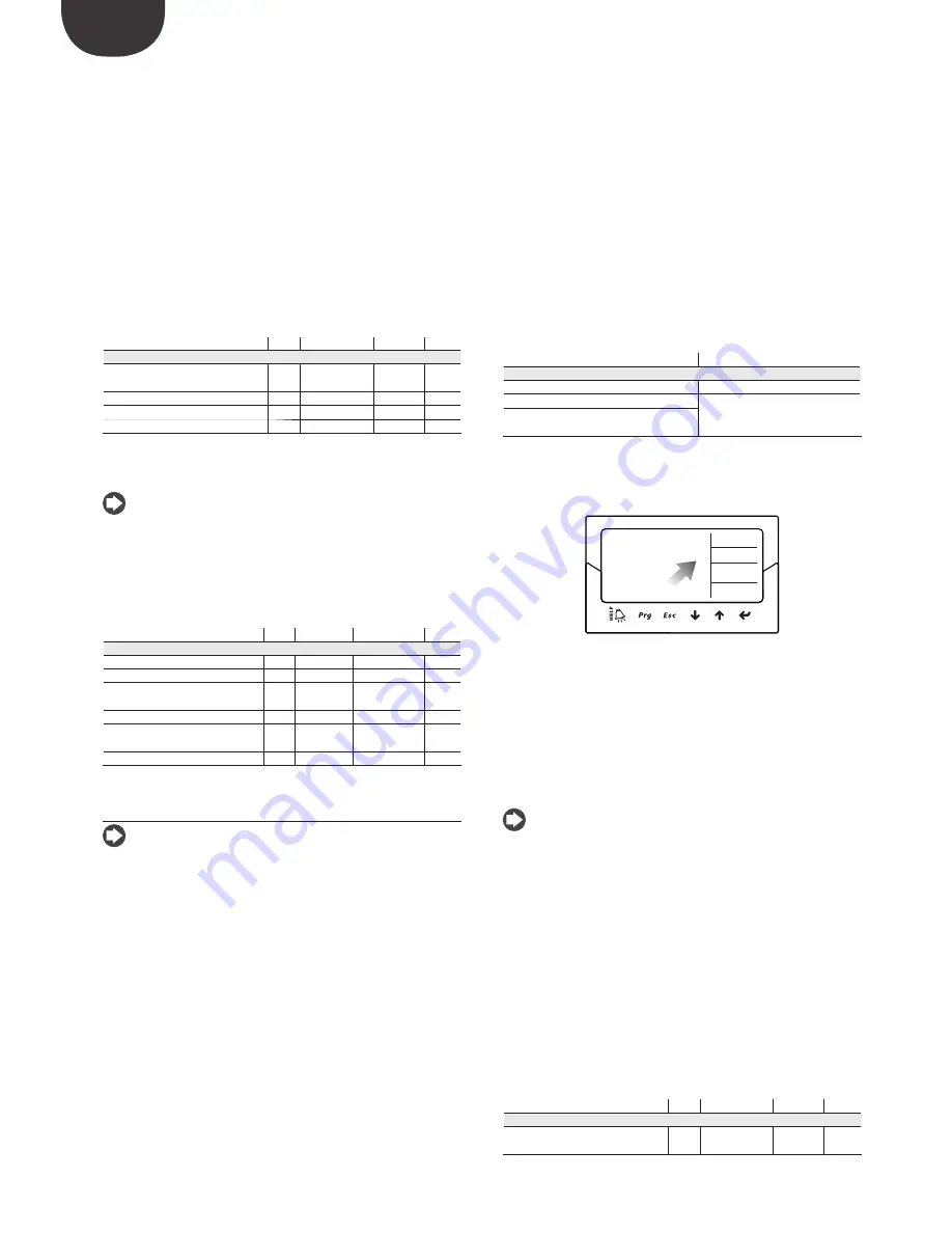
The activation status of the tuning procedure will be shown on the standard 
display by the letter “T”.

Superheating

  4.9 K

Valve opening

  44 %


ON


-- Relais

A/B

T

Fig. 5.d

With adaptive control enabled, the controller constantly evaluates whether 
control is sufficiently stable and reactive; otherwise the procedure for 
optimising the PID parameters is activated. The activation status of the 
optimisation function is indicated on the standard display by the message 
“TUN” at the top right.
The PID parameter optimisation phase involves several operations on the 
valve and readings of the control variables so as to calculate and validate 
the PID parameters. These procedures are repeated to fine-tune superheat 
control as much as possible, over a maximum of 12 hours.

 Note: 

• 

during the optimisation phase maintenance of the superheat set point is 
not guaranteed, however the safety of the unit is ensured through activation 
of the protectors. If these are activated, the procedure is interrupted;

• 

if all the attempts performed over 12 hours are unsuccessful, the “adaptive 
control ineffective” alarm will be signalled and adaptive control will be 
disabled, resetting the default values of the PID and protection function 
parameters;

• 

to deactivate the “adaptive control ineffective” alarm set the value of the 
“main control” parameter to one of the first 10 options. If required, adaptive 
control can be immediately re-enabled using the same parameter. If the 
procedure ends successfully, the resulting control parameters will be 
automatically saved.

A

utotuning

EVD evolution TWIN also features an automatic tuning function (Autotuning) 
for the superheat and protector control parameters, which can be started by 
setting the parameter “Force manual tuning” = 1.

Parameter/Description

Def.

Min.

Max.

UOM

SPECIAL
Force manual tuning
0 = no; 1= yes

0

0

1

-

Tab. 5.e

Summary of Contents for EVD Evolution Twin

Page 1: ...OWER SIGNAL CABLES TOGETHER READ CAREFULLY IN THE TEXT I n t e g r a t e d C o n t r o l S o l u t i o n s E n e r g y S a v i n g s User manual Driver for 2 electronic expansion valves EVD evolution...

Page 2: ......

Page 3: ...he internal circuits and mechanisms may be irreparably damaged do not use corrosive chemicals solvents or aggressive detergents to clean the device do not use the product for applications other than t...

Page 4: ......

Page 5: ...6 Programmable control 26 5 7 Control with refrigerant level sensor 28 6 FUNCTIONS 29 6 1 Power supply mode 29 6 2 Battery charge delay 29 6 3 Network connection 29 6 4 Inputs and outputs 29 6 5 Cont...

Page 6: ......

Page 7: ...he serial port see paragraph 2 9 in place of the service serial port The universal models can drive all types of valves while the CAREL models only drive CAREL valves 1 1 Models Code Description EVD00...

Page 8: ...bcooling measurement high condensing temperature protection HiTcond modulating thermostat subcooling measurement reverse high condensing temperature protection possibility to manage CO2 R744 cascade s...

Page 9: ...N A CLOSE A OPEN B CLOSE B A B COMB NOB 1 3 2 4 A shield TRADRFE240 4 1 2 3 8 9 10 11 12 6 13 14 7 15 16 5 S B 17 18 CAREL EX V VALVE B CAREL EX V VALVE A EVD evolution twin Fig 2 c Key 1 green 2 yell...

Page 10: ...lation environment Important avoid installing the controller in environments with the following characteristics relative humidity greater than the 90 or condensing strong vibrations or knocks exposure...

Page 11: ...he twin 1 controller and the remote option for the other drivers Driver B on the twin3 controller must use another pressure probe P2 Example twin1 twin2 twin3 Probe S1 driver A 0 5 to 7 barg P1 remote...

Page 12: ...EVD evolution twin can be connected to the computer updating the firmware at the same time each controller must have a different network address 2 10 Upload Download and Reset parameters display Proc...

Page 13: ...DI2 VREF Tx Rx GND GND DI1 S4 S3 S2 S1 GND DI2 VREF 1 20 Tx Rx DI1 S4 S3 S2 S1 GND DI2 VREF L 2 Fig 2 o Key 1 green 21 black 2 yellow 22 blue 3 brown 23 computer for configuration supervision 4 white...

Page 14: ...programming operations on the controller 3 2 Display and keypad The graphic display shows two variables for each driver A B the control status of the driver activation of the protectors any alarms an...

Page 15: ...st figure and confirming each figure with ENTER 4 if the value entered is correct the first modifiable parameter is displayed network address 5 press UP DOWN to select the parameter to be set 6 press...

Page 16: ...dby until re enabled with the valve stopped in the last position pCO PROGRAMMABLE CONTROLLER the first operation to be performed if necessary is to set the network address using the display Important...

Page 17: ...arameter in question if the valve and or the pressure probe used are not available in the list select any model and end the procedure Then the controller will be enabled for control and it will be pos...

Page 18: ...the same type A ratiometric probe and an electronic probe cannot be used together Note in the case of multiplexed systems where the same pressure probe is shared between the twin1 and twin2 controller...

Page 19: ...commissioning After commissioning check that the valves complete a full closing cycle to perform alignment set if necessary in Service or Manufacturer programming mode the superheat set point otherwis...

Page 20: ...ver The first 10 settings refer to superheat control the others are so called special settings and are pressure or temperature settings or depend on a control signal from an external controller The la...

Page 21: ...0 can be used shared between driver A and B Ratiometric transducers cannot be shared Another possibility involves connecting two equal valves operation in parallel mode see paragraph 2 5 to the same e...

Page 22: ...d by the user and involves just one optimisation procedure Both procedures give new values to the PID superheat control and protection function parameters PID proportional gain PID integral time PID d...

Page 23: ...ing Digital Scroll compressors allow wide modulation of cooling capacity by using a solenoid valve to active a patented refrigerant bypass mechanism This operation nonetheless causes swings in the pre...

Page 24: ...temperature This control function can be used to control cooling capacity which in the following example is performed by driver B On a refrigerated cabinet if the ambient temperature probe S4 measures...

Page 25: ...V1 Solenoid valve For the wiring see paragraph General connection diagram This involves PID control without any protectors LowSH LOP MOP see the chapter on Protectors without any valve unblock proced...

Page 26: ...and receives the information needed to manage the valves from the pCO Parameter Description Def CONFIGURATION Main control I O expander for pCO multiplexed showcase cold room Tab 5 l TA PA S1 EVD evo...

Page 27: ...mmable control input The function assigned to each input is defined by parameter Programmable control input The parameter has 16 bits and is divided into 4 digits as described in Programmable control...

Page 28: ...ent function f1 S1 f2 S2 f3 S3 f4 S4 Programmable control input_1 4100 Measurement Tdew S1 S2 Programmable control options_1 2140 1 S1 Evaporation pressure 2 S2 Suction temperature 3 S3 Condensing pre...

Page 29: ...d S4 as well as the possibility to calibrate the pressure and temperature signals As regards the choice of pressure liquid probe S1 and S3 see the chapter on Commissioning Inputs S2 S4 The options are...

Page 30: ...EC PRIM SEC 1 PRIM PRIM DI1 DI2 2 PRIM SEC DI1 DI2 DI1 3 SEC PRIM DI2 DI2 DI1 4 SEC SEC Regulation backup driver A supervisor variable DI1 Regulation backup driver B supervisor variable DI2 Note that...

Page 31: ...when the compressor stops or the control solenoid valve closes The valve is closed or open according to the setting of Valve open in standby The percentage of opening is set using Valve position in s...

Page 32: ...dby T1 Pre position time P Pre positioning T2 Start delay after defrost R Control t Time Positioning change cooling capacity This control status is only valid for the pLAN controller If there is a cha...

Page 33: ...closed or fully open position the valve may physically not be in that position The Synchronisation procedure allows the driver to perform a certain number of steps in the suitable direction to realig...

Page 34: ...on of the protector LowSH low superheat The protector is activated so as to prevent the return of liquid to the compressor due to excessively low superheat values Parameter description Def Min Max UOM...

Page 35: ...e trying to stop the superheat from increasing as much as possible Normal operating conditions will not resume based on the activation of the protector but rather on the reduction in the refrigerant c...

Page 36: ...17 Danfoss ETS 250 5 Alco EX7 18 Danfoss ETS 400 6 Alco EX8 330Hz recommend CAREL 19 Two EX V CAREL connected together 7 Alco EX8 500Hz specific Alco 20 Sporlan SER I G J K 8 Sporlan SEI 0 5 11 21 Da...

Page 37: ...24 Programmable positioner 25 Evaporator liquid level regulation with CAREL sensor 26 Condenser liquid level regulation with CAREL sensor only for controls for CAREL valves common parameter between d...

Page 38: ...city 4 Set point control 5 Superheat 6 Suction temperature 7 Evaporation temperature 8 Evaporation pressure 9 Condensing temperature 10 Condensing pressure 11 Modulating thermostat temperature 12 EPR...

Page 39: ...e S1 MINIMUM alarm value 200 2900 barg psig A 37 36 CO C S2 calibration offset 0 20 36 20 20 36 20 C F volt A 41 40 CO C S2 calibration gain 0 to 10 V 1 20 20 A 43 42 CO C Temperature S2 MINIMUM alarm...

Page 40: ...A HiTcond threshold SELECT WITH PROG CONT 80 85 121 200 392 C F A 58 57 C HiTcond integral time SELECT WITH PROG CONT 20 0 800 s A 57 56 A Modulating thermostat set point SELECT WITH PROG CONT 0 85 12...

Page 41: ...57 32768 32767 I 129 256 Bubble f low 17253 32768 32767 I 130 257 C Faulty closure alarm status 0 1 no yes 0 0 1 D 49 48 C Battery charge delay 0 0 250 min I 135 262 CO ALARM CONFIGURATION C Low super...

Page 42: ...s ETS 250 5 Alco EX7 18 Danfoss ETS 400 6 Alco EX8 330Hz recommend CAREL 19 Two EX V CAREL connected together 7 Alco EX8 500Hz specific Alco 20 Sporlan SER I G J K 8 Sporlan SEI 0 5 11 21 Danfoss CCM...

Page 43: ...rammable positioner 25 Evaporator liquid level regulation with CAREL sensor 26 Condenser liquid level regulation with CAREL sensor control only settable on driver A however corresponds to the entire c...

Page 44: ...acity 4 Set point control 5 Superheat 6 Suction temperature 7 Evaporation temperature 8 Evaporation pressure 9 Condensing temperature 10 Condensing pressure 11 Modulating thermostat temperature 12 EPR...

Page 45: ...ssure S1 MINIMUM alarm value 200 2900 barg psig A 37 36 CO C S2 calibration offset 0 20 36 20 20 36 20 C F volt A 41 40 CO C S2 calibration gain 0 to 10 V 1 20 20 A 43 42 CO C Temperature S2 MINIMUM a...

Page 46: ...ROG CONT 80 85 121 200 392 C F A 58 57 CO C HiTcond integral time SELECT WITH PROG CONT 20 0 800 s A 57 56 CO A Modulating thermostat set point SELECT WITH PROG CONT 0 85 121 200 392 C F A 61 60 CO A...

Page 47: ...suction temperature alarm threshold 50 85 121 200 392 C F A 97 96 C Low suction temperature alarm delay 0 alarm disabled 300 0 18000 s I 65 192 VALVE C EEV minimum steps 50 0 9999 step I 66 193 C EEV...

Page 48: ...A 111 110 R Liquid regulation evaporator condenser level percentage 0 0 100 A 116 115 R Valve position 0 0 9999 I 4 131 R Current unit cooling capacity 0 0 100 I 7 134 R W Adaptive control status 0 1...

Page 49: ...cooling capacity 0 0 100 I 50 177 R W EVD status 0 0 20 I 51 178 R Protector status 0 0 5 I 52 179 R Control mode 1 1 26 I 73 200 R W Adaptive control status 0 0 6 I 77 204 R Last tuning result 0 0 8...

Page 50: ...ration pressure Condensing temperature Condensing pressure Modulating thermostat temperature EPR pressure back pressure Hot gas bypass pressure Hot gas bypass temperature CO2 gas cooler outlet tempera...

Page 51: ...to the corresponding driver 3 press Help to display the required alarm queue the control alarms can be disabled by setting the corresponding delay to zero Table of alarms Type of alarm Cause of the al...

Page 52: ...S3 alarm manage ment parameters Check the probe connections Check the parameters Probe S1 S3 alarm management and Pressure S1 S3 MINIMUM and MAXIMUM alarm values Temperature difference Maximum pressu...

Page 53: ...rced to the initial position control stopped Parameter description Def Min Max UOM CONFIGURATION Probe S1 alarm management 1 No action 2 Forced valve closing 3 Valve in fixed position 4 Use backup pro...

Page 54: ...ng powered up the controller forced closing of the valve is performed immediately Important after having resolved the problem with the motor it is recommended to switch the controller off and on again...

Page 55: ...percussions on the control temperature Liquid returns to the com pressor only after defrosting for multiplexed showcases only The pause in control after defrosting is too short for MasterCase MasterCa...

Page 56: ...culation in reference to the ratio between the rated cooling capacity of the evaporator and the capacity of the valve if necessary lower the value The unit switches off due to low pressure during cont...

Page 57: ...n 0 1 fs measurement error 2 fs maximum 1 typical electronic pressure probe 4 to 20 mA resolution 0 5 fs measurement error 8 fs maximum 7 typical remote electronic pressure probe 4 to 20mA Maximum num...

Page 58: ...12 a Then the user can choose to 1 directly access the list of parameters for the EVD evolution twin saved to EEPROM select tLAN This is done in real time ONLINE mode at the top right set the network...

Page 59: ...code Different firmware versions may cause compatibility problems 12 4 Setting the default parameters When the program opens select the model from the range and load the associated list of parameters...

Page 60: ...aporation pressure probe S1 and the suction temperature probe S2 which will be fitted after the evaporator and digital input 1 2 to enable control As an alternative to digital input 1 2 control can be...

Page 61: ...o 20 mA probe and then manually modify the minimum and maximum measurement in the manufacturer parameters corresponding to the probes Important probes S3 and S4 are shown as NOT USED if the auxiliary...

Page 62: ...elow This type of control must be used with care due to the lower precision of the temperature probe compared to the probe that measures the saturated evaporation pressure Parameter Description Def CO...

Page 63: ...ctor but rather on the reduction in the outside temperature The system will therefore remain in the best operating conditions a little below the threshold until the environmental conditions change t t...

Page 64: ...d temperature probe S4 will be used to replace probes S1 and S2 respectively in the event of faults on one or both so as to guarantee a high level of reliability of the controlled unit S2 S4 S3 S1 EVD...

Page 65: ...alve The ratio between the integral times of these two concurrent yet opposing protectors determines how effective one is compared to the other Reverse HiTcond for CO2 cascade systems Reverse high con...

Page 66: ...ENG EVD Evolution TWIN 0300006EN rel 2 6 31 01 2019 66 Note...

Page 67: ......

Page 68: ...L INDUSTRIES HQs Via dell Industria 11 35020 Brugine Padova Italy Tel 39 049 9716611 Fax 39 049 9716600 e mail carel carel com www carel com Agenzia Agency EVD Evolution TWIN 0300006EN rel 2 6 31 01 2...

Reviews: