


34
ENG
ir0300028EN rel. 1.1 - 05.05.2017
Example:
if there is an RTC fault, the defrost programmed by td3 is not
performed, and after the safety time dI a new defrost starts.
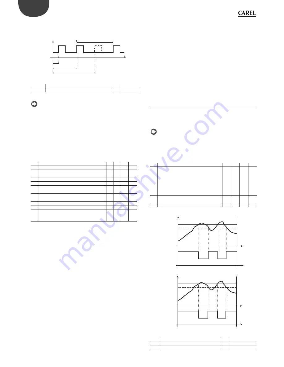
ON
OFF
DEF
t
td1
td2
dI
td3
Fig. 6.r
Key
dI
Maximum time between consecutive defrosts DEF Defrost
td1…td3 Programmed defrosts
t
Time
Note:
•
if dI expires when the controller is OFF, a defrost will be performed
when next switched on;
•
to ensure regular defrosts, the interval between defrosts must be
greater than the maximum defrost duration, plus the dripping time
and post-dripping time;
•
if “dI”=0 and no timed defrosts have been set, defrosts can only be
performed at power on, from digital input, from the supervisor and
from the keypad.
O
ther defrost parameters
Par. Description
Def Min Max UOM
d3
Defrost activation delay
0
0
250 min
d4
Defrost at start-up
0/1=disabled/enabled
0
0
1
-
d5
Defrost delay at start-up (if d4=1) or from dI
0
0
250 min
dd
Dripping time after defrost (fans off )
2
0
15
min
d8
High temperature alarm bypass time after
defrost (and door open)
1
0
250 min
d9
Defrost priority over compressor protectors 0/1
= yes/no
0
0
1
-
d/1 Display defrost probe 1
-
-
-
°C/°F
d/2 Display defrost probe 2
-
-
-
°C/°F
dC
Time base for defrost
0 = dI in hours, dP1 and dP2 in minutes
1 = dI in minutes, dP1 and dP2 in seconds
0
0
1
-
Tab. 6.l
•
d3 determines the time that must elapse, when the defrost is activated,
between the stopping of the compressor (heater defrost) or the
starting of the compressor (hot gas defrost), and the activation of the
defrost relays on the main and auxiliary evaporators;
•
d4 determines whether to activate a defrost when switching controller
on. The defrost call at start-up has priority over activation of the
compressor and the continuous cycle. Defrosting when switching
controller on may be useful in special situations.
Example:
there are frequent power failures in the system. In the event of a
power failure, the instrument resets the internal clock that calculates the
interval between two defrosts, starting from zero again. If the frequency
of the power failure were, in an extreme case, greater than the defrost
frequency (e.g. a power failure every 8 hours, against a defrost every 10
hours) the controller would never perform a defrost. In a situation of this
type, it is preferable to enable defrost on start-up, above all if the defrost is
controlled by temperature (probe on the evaporator), therefore avoiding
unnecessary defrosts or at least reducing the running times. For systems
with a large number of units, if selecting defrosts at start-up, after a power
failure, all the units will start a defrost. This may cause voltage overloads.
To overcome this, parameter ‘d5’ can be used, which adds a delay before
the defrost; the delay must obviously must be diff erent for each unit.
•
d5 represents the time that must elapse between the start-up of the
controller and the start of the defrost on start-up;
•
dd is used to force the stop of the compressor and of the evaporator
fan after a defrost so as to assist the dripping of the evaporator same.
•
d8 indicates the high temperature alarm signal bypass time after
the end of a defrost or when opening the door, if the digital input is
connected to the door switch;
•
d9 overrides the compressor protection times c1, c2, c3 at the start of
the defrost;
•
d/1 and d/2 are used respectively to display the values read by defrost
probe 1 and 2;
•
dC is used to change the unit of measure (hours or minutes) used to
count the times for parameters dI (defrost interval, hours or minutes,),
dP1 and dP2 (defrost duration).
6.10 Evaporator fans
The evaporator fans can be managed according to the temperature
measured by the defrost and control probes. The deactivation threshold
is equal to the value of parameter F1, and the hysteresis is equal to the
value of A0.
Note:
during the dripping time and post-dripping time, if set, the
evaporator fans are always off
Below are the parameters involved in managing the evaporator fans, and
an example of the trend based on the diff erence between the evaporator
temperature and the value of the virtual probe (F0=1). If F0=2, activation
depends solely on the evaporator probe temperature.
Par. Description
Def
Min Max UOM
F0
Evaporator fan management
0 = always on
1 = activation based on Sd-Sv (diff erence
between virtual probe and evaporator
temperature)
2 = activation based on Sd (evaporator
temperature)
0
0
2
-
F1
Fan activation temperature (only if F0 = 1
or 2)
5.0
-50
200
°C/°F
A0
Alarm and fan diff erential
2.0
0.1
20
°C/°F
Tab. 6.m
F0=1
ON
OFF
FAN
F1
Sd - Sv
F1-A0
t
t
F0=2
ON
OFF
FAN
F1
Sd
F1-A0
t
t
Fig. 6.s
Key
Sd
Defrost probe
A0
Diff erential
FAN
Evaporator fans
t
Time
F1
Fan activation temperature
Sv
Virtual probe
Summary of Contents for easy small wide
Page 2: ......
Page 4: ...4 ENG ir33plus 0300028EN rel 1 1 05 05 2017...
Page 6: ...6 ENG ir33plus 0300028EN rel 1 1 05 05 2017...
Page 55: ......