5
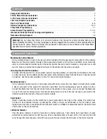
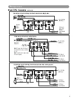
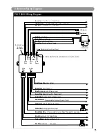
Black/White Wire: (Programmable Output. Default Setting Domelight Supervision )
The Black/White wire is a low current (300mA) grounded output wire that is pre-programmed to activate the
vehicle’s interior lighting system when the security system is disarmed. An additional relay may be required for
proper installation (See Optional Accessory Connection for proper wiring). This wire can also be programmed to
operate as a channel #4 output (See Alarm Feature Programming Part 2 for programming instructions)
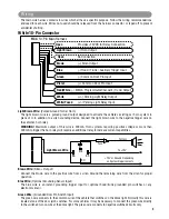
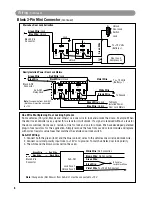
Red Wire: (Main Power Input)
Connect the red wire directly to the (+) battery post for best operation of the alarm system. For best current
sensing capability from the alarm’s current sensing circuit, connect the red wire to the constant power wire
coming from the interior dome light.
Black Wire: (Main Ground Input)
Connect the black wire directly to the frame of the vehicle. Use a bolt and nut to secure the wire. Scrape away
any grease or paint that might prevent a good connection.
Yellow Wire: (Sw12 Volts From the Ignition Switch)
Connect the yellow wire to a +12 volt wire that is switched on and off by the ignition key. The correct wire will
in12 volts when the ignition key is in the on and start positions. Do not connect the yellow wire to the
“ACC” wire coming from the ignition switch.
White 5-Pin Connector
(Continued)
White 2-Pin Connector
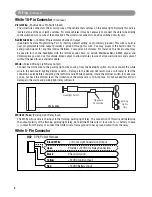
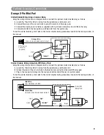
LED Status Indicator:
The LED indicator status should be mounted in a highly visible area such as top of the dashboard, on top of
the shifter console or on dashboard face. Leave at least 6mm space behind the mounting location for LED
housing. Once a suitable location is chosen, drill a 1/4” hole. Run the LED wires though the hole then press
the LED housing into the place. Route the LED wires to the control module.
Blue 2-Pin Connector
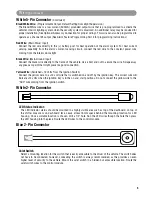
Valet Switch
Select a mounting location for the switch that is easily accessible to the driver of the vehicle. The switch does
not have to be concealed, however, concealing the switch is always recommended, as this provides an even
higher level of security to the vehicle. Mount the valet switch in a hidden but accessible location. Route the
valet switch wires to the control module.
Wiring
(Continued)
PLUS-4900-IM.qxp 4/30/09 3:06 PM Page 5


