background image

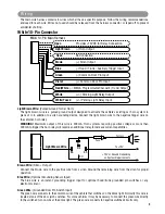
The main wire harness contains 8 wires which all have a specific purpose. Follow the wiring recommendations

enclosed for each wire. Wires not used should be released from the harness connector or taped off to prevent

accidental shorting. 

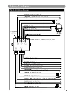
HC4  10-Pin Main Harness

Light Brown 

(-) Horn Output

Green 

(-) Common Door Pin Input

Violet 

(+) Common Door Pin Input

Blue 

(-) Hood / Trunk / Auxiliary Trigger Input

Red/White (-) 300mA Programmable Channel 3 (Trunk) Output

White 

(+/-) Parking Light Relay Output

Brown 

(+) Siren Output

White/Fused 

(+/-) Parking Light Relay Input

Open                  No Connection

Open                    Pr12VDC for Relay Connection

Light Brown Wire: (Pulsed Ground for Car Horn)

The light brown wire is a pulsed ground output designed to activate the vehicle’s existing car horn system in

place of or in addition to a siren sounding device. Connect the light brown wire to the negative trigger wire on

the vehicle’s horn relay.
WARNING! Maximum output of this wire is 300mA. Horn systems requiring positive voltage or more than

300mA to trigger the horn relay will require an additional relay to increase current capabilities.

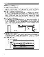
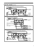
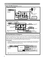
White 10-Pin Connector

87

87a

86

85

30

Light Brown Wire

To +12V

To Horn

+12V or Ground Depending 

on System Requirements

Fuse

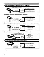
Brown Wire: (Siren + Output)

Connect the brown wire to the positive wire from a siren. Ground the remaining wire from the siren for proper

operation.

Blue Wire: (Optional Grounding Sensor Input)

The blue wire is an instant grounding trigger input for optional hood/trunk grounded pin switches or any

electronic sensor.

Green Wire: (Grounded Door Pin Switch Input)

The green wire connects to the common wire of the vehicle that switches on the dome light. Normally this wire is

located at one of the door jamb switches. For some vehicles it may be necessary to connect the green wire directly

to the switched turn on wire at the dome light. The green wire connects to negative switched circuits only.

Wiring

PLUS-4900-IM.qxp  4/30/09  3:06 PM  Page 3

Summary of Contents for PLUS-4900

Page 1: ...wo conditions 1 This device may not cause harmful interference and 2 This device must accept any interference received including interference that may cause undesired operation Note The manufacturer i...

Page 2: ...ound path to the ground for maximum siren effect Use the self tapping screws to secure the siren Connect the Black wire from the siren to the frame of the vehicle In many cases you can connect the Bla...

Page 3: ...wire on the vehicle s horn relay WARNING Maximum output of this wire is 300mA Horn systems requiring positive voltage or more than 300mA to trigger the horn relay will require an additional relay to...

Page 4: ...e headlights with the remote control Also on certain Mercedes Benz BMW Jaguar and Volkswagens you can use this unique timed output to allow remote closure of all power windows and sunroof without the...

Page 5: ...itched 12 Volts From the Ignition Switch Connect the yellow wire to a 12 volt wire that is switched on and off by the ignition key The correct wire will indicate 12 volts when the ignition key is in t...

Page 6: ...em Lock Out Ground Input Unlock Out To Door Lock Control Relays Lock Control Switch Blue Wire Connect to Unlock Green Wire Connect to Lock Black 3 Pin Mini Connector Unlock Driver s Door First for 3 W...

Page 7: ...wn still applies Black 3 Pin Connector Continued Unlock Driver s Door First Wiring for 3 Wire Positive Door Locking Systems 87 87A 85 86 30 87 87A 85 86 30 To 12 Volts Battery To Power Door Lock Switc...

Page 8: ...door lock polarity 3 The white and the brown wires will not be used White Wire No Connection Brown Wire No Connection Green Wire Blue Wire Violet Wire To 12 Volts Constant Lock Fuse 1 Unlock Fuse 2 A...

Page 9: ...Ground when Armed Alarm Output 2 Pin Orange Connector Supplied 87 87a 86 85 30 ACC START OFF IGN Cut Black Black Starter Starter Disable Wiring Using ALA RPS Relay Pack Using the wiring information an...

Page 10: ...y Pack Orange Wire Output to Trunk Switch Purple Wire Input to Relay or Insert Red Wire into the First Socket Insert Black Wire into the Eighth Socket Black Wire Power Trunk Activation Using Optional...

Page 11: ...turn off the ignition key or wait for 15 seconds to get out of transmitter programming mode You will hear 1 short 1 long chirps beeps to indicate you are out of the transmitter programming mode OFF Ex...

Page 12: ...nual Arming Automatic Rearm Off Automatic Rearm On Instant Door Ajar Warning 45 Seconds Delay Door Ajar Warning Car Jack Mode Off Manual Car Jack Mode Automatic Car Jack Mode Door Ajar Warning Off Ins...

Page 13: ...Some vehicles have a special Comfort Feature When you lock the door with the key you have to hold the key in the lock position for about 5 to 7 seconds and the windows will close automatically If you...

Page 14: ...chirp 1time 2 Rotate the sensitivity adjuster Clockwise to increase the impact sensitivity 3 Rotate the sensitivity adjuster Counterclockwise to decrease the impact sensitivity Turn the ignition swit...

Page 15: ...e Channel 3 Ouput Trunk 5A Starter Disable Port See Optional Accessory Connection 2 Pin White LED Indicator Valet Switch Green Wire Warn Away Ground Trigger Blue Wire Zone 4 Ground Trigger Black Wire...

Page 16: ...PLUS 4900 IM 4 30 09 Rev A Copyright 2009 Magnadyne Corporation R Automotive Security...

Reviews: