15
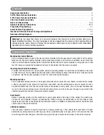
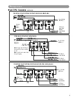
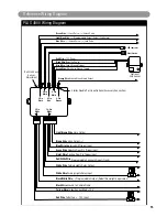
5-Pin
White
10-Pin
White
2-Pin
Orange
Black Wire Ground to Vehicle Frame
Yellow Wire to Ignition Sw12 V
Red Wire To B 12V Input
Light Brown Wire Horn Output
Brown Wire Siren Output (+)
Blue Wire Negative AUX Trigger Input
Violet Wire Positive Door Pin Trigger Input
White Wire Parking Lights Relay Output
10A
White Wire Parking Lights Relay Input
Green Wire Negative Door Pin Trigger Input
Programmable Channel 3 Ouput (Trunk)
5A
Starter Disable Port (See Optional Accessory Connection)
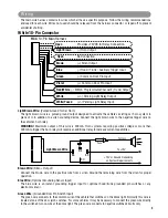
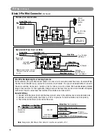
2-Pin
White
LED Indicator
Valet Switch
Green Wire: Warn Away Ground Trigger
Blue Wire: Zone 4 Ground Trigger
Black Wire: Negative Power
Red Wire: +12V Power
Green Wire : (-) Lock Pulse - (+) Unlock Pulse
Blue Wire : (-) Unlock Pulse - (+) Lock Pulse
Light Blue Wire : (-) Programmable Output (Default 2nd Unlock)
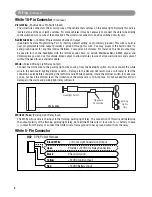
2-Pin
Blue
4-Pin
White
3-Pin
Black
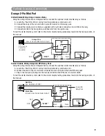
PLUS 4900 Wiring Diagram
Red/WhiteWire
(-) Programmable Output (Default Domelight Supervision)
Black/WhiteWire
Orange Wire:Ground When Armed Output
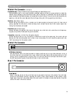
Optional
2nd Sensor
Built-In Shock
Sensor
Adjustment
Reference Wiring Diagram
PLUS-4900-IM.qxp 4/30/09 3:06 PM Page 15


