2
Component Installation . . . . . . . . . . . . . . . . . . . . . . . . . . . . . . . . . . . . . . . . . . . . . . . . . . . . . . . . . . . . . 2
10-Pin Main Harness Installation . . . . . . . . . . . . . . . . . . . . . . . . . . . . . . . . . . . . . . . . . . . . . . . . . . . . . 3
5-Pin Power Harness Installation . . . . . . . . . . . . . . . . . . . . . . . . . . . . . . . . . . . . . . . . . . . . . . . . . . . . . . 4
LED, Valet Switch Connection . . . . . . . . . . . . . . . . . . . . . . . . . . . . . . . . . . . . . . . . . . . . . . . . . . . . . . . . 5
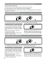
Door Lock Connections . . . . . . . . . . . . . . . . . . . . . . . . . . . . . . . . . . . . . . . . . . . . . . . . . . . . . . . . . . . . 6-8
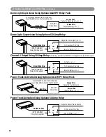
Optional Accessory Connections . . . . . . . . . . . . . . . . . . . . . . . . . . . . . . . . . . . . . . . . . . . . . . . . . . . . 9-10
Transmitter Programming . . . . . . . . . . . . . . . . . . . . . . . . . . . . . . . . . . . . . . . . . . . . . . . . . . . . . . . . . . 11
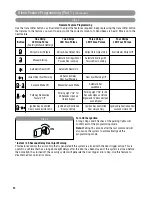
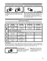
Alarm Feature Programming . . . . . . . . . . . . . . . . . . . . . . . . . . . . . . . . . . . . . . . . . . . . . . . . . . . . . . 11-13
Internal and External Sensor Testing and Adjustment . . . . . . . . . . . . . . . . . . . . . . . . . . . . . . . . . . . . . 14
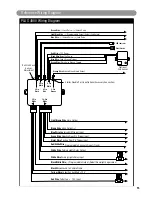
Reference Wiring Diagram . . . . . . . . . . . . . . . . . . . . . . . . . . . . . . . . . . . . . . . . . . . . . . . . . . . . . . . . 15
Mounting the Control Module:
Find a suitable location to secure the alarm control module within the passengers compartment of the vehicle.
Never mount the alarm control module in the engine compartment or in the trunk. In addition, never mount the
alarm control module in the direct path of the heater. Secure the alarm control module by using wire ties or drill
two 1/8" holes and secure the module to the frame of the vehicle with the screws provided.
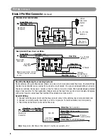
Installing Hood/ Trunk Pin Switches:
Provided with the alarm kit is one pin switch and one mounting bracket. To install the switch either in the truck
or under the hood, find a suitable location where the switch will make contact with the hood or trunk lid and will
not get wet. Use the bracket provided or drill a 1/4" hole in the desired location.
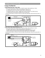
Mounting the Siren:
Find a suitable mounting location in the engine compartment to secure the siren. Select a location that provides
a direct sound path to the ground for maximum siren effect. Use the self-tapping screws to secure the siren.
Connect the Black wire from the siren to the frame of the vehicle. In many cases, you can connect the Black wire
to one of the siren mounting screws. Run the remaining brown wire from the siren through a grommet in the
vehicle firewall to the location of the alarm control module.
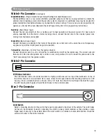
Valet Switch
Select a mounting location for the switch that is easily accessible to the driver of the vehicle. The switch does
not have to be concealed. However, concealing the switch is always recommended, as this provides an even
higher level of security to the vehicle. Mount the valet switch in a hidden but accessible location. Route the valet
switch wires to the control module.
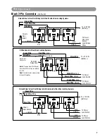
LED Status Indicator
The LED status indicator should be mounted in a highly visible area. Their should be at least 6mm of space
behind the mounting location for LED housing. Once a suitable location is chosen, drill a 1/4" hole. Run the LED
wires through the hole then press the LED housing into the place. Route the LED wires to the control module.
Warning! Do not plug the 10-pin or 5-pin wire harness into the alarm control module before you
begin installing the alarm. The wire harnesses must be plugged into the alarm control module after all
connections are made. Failure to follow this procedure could cause some confusion with transmitter
operation and or alarm function operation.
Contents
Component Installation
PLUS-4900-IM.qxp 4/30/09 3:06 PM Page 2

