


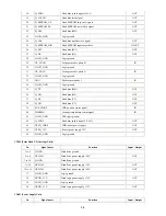
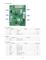
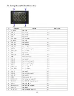

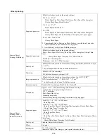


CN905 (to/from NCU Sub Board)
CN906 (SUB1, to/from NCU Sub Board)
CN909 (SUB2, to NCU Sub Board, for Speaker)
5
CMLD
CML relay drive signal (1: ON 0: OFF)
OUT
6
HRD
H relay drive signal (1: ON (no ring) 2: OFF (ring))
IN
7
CI1
CI detect signal 1 (1: CI 0: No CI)
IN
8
+3.3V
Digital power supply
IN
9
IPSEL
Terminal switch signal
-
10
D_GND
Digital ground
-
11
SNOOP
Snoop signal
IN
12
TX
4-wire analog transmission signal
OUT
13
RX
4-wire analog reception signal
IN
14
+12V
Analog power supply
-
15
A_GND
Analog ground
-
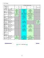
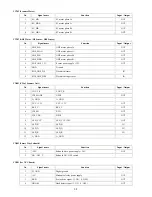
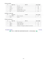
No.
Signal name
Function
Input / Output
1
SPSTP
Speaker stop signal
OUT
2
BUZZER
Keypad/Alarm volume control
OUT
3
SCAN_OPEN
Scanner open switch signal
IN
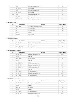
4
GND
Ground
-
5
DIA0
Diode sensor anode 0
OUT
6
DIA1
Diode sensor anode 1
OUT
7
DIODE0
Diode sensor signal 0
IN
8
DIODE1
Diode sensor signal 1
IN
9
+5V
VCC +5V
OUT
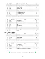
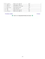
No.
Signal name
Function
Input / Output
1
+3.3V
VCC +3.3V
OUT
2
UH1DP
PictBridge D+ signal
BUS
3
UH1DM
PictBridge D- signal
BUS
4
PPON
PictBridge VBUS power supply
OUT
5
OCI
Over current detect signal
IN
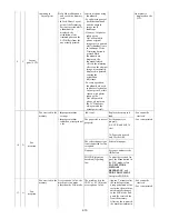
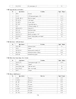
No.
Signal name
Function
Input / Output
1
RX
Line monitor signal
OUT
2
SPSEL2
Volume control signal 2
OUT
3
SPSEL1
Volume control signal 1
OUT
4
SPSEL0
Sound source select signal (Keypad/Alarm or Line monitor)
OUT
To the table of contents
To the top
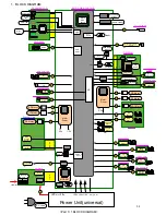
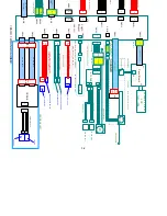
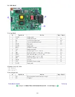
<Part 3: 3. CONNECTOR LOCATION AND PIN LAYOUT; 3-1. Logic Board Ass'y>
3-8
Summary of Contents for PIXMA MP530
Page 5: ...Part 1 MAINTENANCE ...
Page 34: ... Right side c Disconnect the connector for the solenoid 1 29 ...
Page 51: ... Service test print sample 1 46 ...
Page 56: ... System data list sample 1 51 ...
Page 57: ... Error transmission report sample 1 52 ...
Page 60: ...Part 2 TECHNICAL REFERENCE ...
Page 73: ...Part 3 APPENDIX ...