


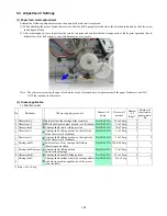


(3) Waste ink counter setting
Before replacement of the logic board ass'y, check the waste ink amount. After the logic board ass'y is replaced, set the waste
ink amount to the replaced logic board ass'y.
In addition, according to the waste ink amount, replace the waste ink absorber (ink absorber kit). When the waste ink absorber is
replaced, reset the waste ink counter (to "0%").
How to check the waste ink amount:
See
3-4. Verification Items, (1) Service test print
, or
(2) EEPROM information print.
How to set the waste ink amount:
See
3-3. Adjustment / Settings, (6) Service mode, "Waste ink amount setting procedures."
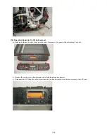
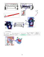
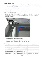
(4) White sponge sheet attachment
Position one of the corners of the white sponge sheet at the scanning reference point on the platen glass
(back left where the blue lines cross in the photo below). Peel off the cover sheet from the double-sided
adhesive tape, and slowly close the document cover with the sponge frame on. The sponge sheet will
attach to the sponge frame.
Open the document cover to confirm the following:
- No extension of the sponge edges over the mold part of the document cover.
- No gap between the platen glass reference edges and the corresponding sponge edges.
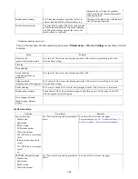
(5) User mode
Function
Procedures
Remarks
Print head manual cleaning
See "Standalone machine operation" below, or
perform from the MP driver Maintenance tab.
Print head deep cleaning
See "Standalone machine operation" below, or
perform from the MP driver Maintenance tab.
Paper feed roller cleaning
See "Standalone machine operation" below.
Nozzle check pattern printing
See "Standalone machine operation" below, or
perform from the MP driver Maintenance tab.
Print head alignment
(automatic / manual)
See "Standalone machine operation" below, or
perform from the MP driver Maintenance tab.
In Custom Settings of the MP driver
Maintenance tab, manual print head
1-39
Summary of Contents for PIXMA MP530
Page 5: ...Part 1 MAINTENANCE ...
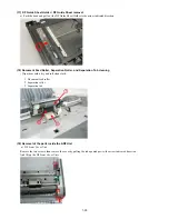
Page 34: ... Right side c Disconnect the connector for the solenoid 1 29 ...
Page 51: ... Service test print sample 1 46 ...
Page 56: ... System data list sample 1 51 ...
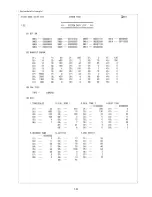
Page 57: ... Error transmission report sample 1 52 ...
Page 60: ...Part 2 TECHNICAL REFERENCE ...
Page 73: ...Part 3 APPENDIX ...