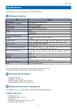


• Service switchboard
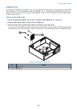
• Chassis fan
• Power supply
• Storage Device
For information about replacing other components, see the documentation that accompanies your printer.
IMPORTANT:
Be sure to use an ESD grounding wrist strap and follow standard ESD (electrostatic discharge) precautions while performing
these procedures. For details, see
NOTE:
There may be tie-wraps used to secure the cables to the chassis. If necessary, cut these tie-wraps before removing the
components.
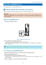
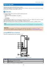
■ Printer interface board
The printer interface board provides the print interface between the
imagePRESS Server
and the printer. The printer interface
board processes the image data and sends it to the printer through the printer interface cable. It is installed in PCIE x16 slot on
the motherboard.
IMPORTANT:
Make sure that the switch on the printer interface board is positioned to 1-3m side of the switch.
2
3
4
1
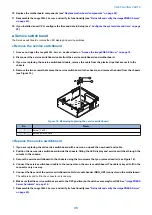
Figure 6: Printer interface board
No.
Name
1
Switch (positioned to 1-3m)
2
Printer interface cable connector
3
PCIE x16 connector
4
J351 connector for 10-pin power button cable to motherboard J29
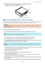
● Remove the printer interface board
1. Access and open the
imagePRESS Server
, as described in (see
“Accessing the imagePRESS Server” on page 18
).
2. Remove the 10-pin power button cable from J351 connector that connects between the printer interface board and
the motherboard.
3. REPLACING PARTS
21
Summary of Contents for P 400
Page 7: ...Introduction 1 Introduction 2 Specifications 7...
Page 16: ...Using the imagePRESS Server 2 Using the imagePRESS Server 11...
Page 21: ...REPLACING PARTS 3 Replacing parts 16...
Page 51: ...INSTALLING SYSTEM SOFTWARE 4 Installing system software 46...


